Toyota Tacoma (2015-2018) Service Manual: Lock Switch Circuit
WIRING DIAGRAM
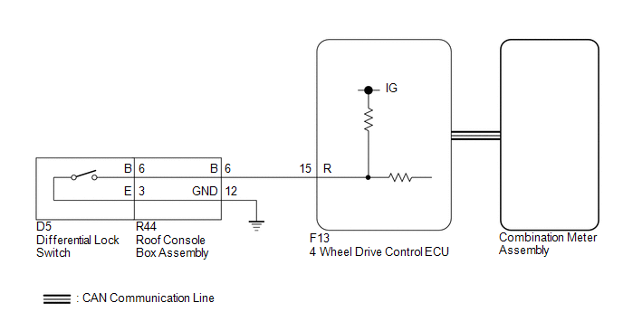
PROCEDURE
|
1. |
CHECK REAR DIFFERENTIAL LOCK INDICATOR LIGHT |
(a) Turn the ignition switch to ON.
(b) for 4WD:
Finish switching to L4.
(c) Check the rear differential lock indicator light.
(d) Press the differential lock switch.
(e) After 60 seconds, check the rear differential lock indicator light.
Result|
Result |
Proceed to |
|---|---|
|
Rear differential lock indicator light blinks or illuminates |
A |
|
Rear differential lock indicator light remains off regardless of switch operation |
B |
|
Rear differential lock indicator light remains illuminated regardless of switch operation |
C |
|
Rear differential lock indicator light rapidly blinks |
D |
- Blinking: Blinks at 0.5 second intervals (0.5 seconds on and 0.5 seconds off)
- Rapidly blinking: Blinks at 0.25 second intervals (0.25 seconds on and 0.25 seconds off)
| A | .gif) |
END |
| C | |
GO TO STEP 8 |
| D | |
GO TO DTC P17CC |
|
.gif)
|
2. |
CHECK CAN COMMUNICATION LINE |
(a) Select "Bus Check" from the System Selection Menu screen, and follow the
prompts on the screen to inspect the CAN Bus (See page
.gif) ).
).
OK:
"Bus Check" indicates no malfunctions in CAN communication.
| NG | |
CHECK CAN COMMUNICATION SYSTEM |
|
|
3. |
READ VALUE USING TECHSTREAM (REAR DIFFERENTIAL LOCK SWITCH CONTROL SW (R)) |
(a) Turn the ignition switch off.
(b) Connect the Techstream to the DLC3.
(c) Turn the Techstream on.
(d) Turn the ignition switch to ON.
(e) Enter the following menus: Powertrain / Four Wheel Drive / Data List.
(f) According to the display on the Techstream, read the Data List.
Four Wheel Drive|
Tester Display |
Measurement Item/Range |
Normal Condition |
Diagnostic Note |
|---|---|---|---|
|
Rear Differential Lock Control SW (R) |
Differential lock switch status (differential lock switch input signal of R terminal on ECU side)/ ON or OFF |
ON: Switch pressed and held OFF: Switch not pressed |
- |
OK:
Display changes according to differential lock switch operation.
| NG | |
GO TO STEP 5 |
|
|
4. |
INSPECT COMBINATION METER ASSEMBLY |
(a) Turn the ignition switch off.
(b) Perform Active Test of the combination meter assembly using the Techstream.
(c) Check the combination meter assembly.
OK:
The rear differential lock indicator light turns on or off in accordance with the Techstream.
| OK | |
REPLACE 4 WHEEL DRIVE CONTROL ECU |
| NG | |
CHECK METER / GAUGE SYSTEM |
|
5. |
INSPECT DIFFERENTIAL LOCK SWITCH |
(a) Disconnect the G13 differential lock switch connector.
|
(b) Measure the resistance according to the value(s) in the table below. Standard Resistance:
|
|
.png)
| NG | |
REPLACE DIFFERENTIAL LOCK SWITCH |
|
|
6. |
INSPECT ROOF CONSOLE BOX ASSEMBLY |
(a) Remove the roof console box assembly.
- for Double Cab: (See page
)
- for Access Cab: (See page
)
.png) Text in Illustration
Text in Illustration
|
*a |
Component without harness connected (Roof Console Box Assembly) |
- |
- |
(b) Measure the resistance according the value(s) in the table below.
Standard Resistance:
|
Tester Connection |
Condition |
Specified Condition |
|---|---|---|
|
R44-6 (B) - 6 (B) |
Always |
Below 1 Ω |
|
R44-12 (GND) - 3 (E) |
Always |
Below 1 Ω |
|
Result |
Proceed to |
|---|---|
|
OK |
A |
|
NG (for Double Cab) |
B |
|
NG (for Access Cab) |
C |
| B | |
REPLACE ROOF CONSOLE BOX ASSEMBLY |
| C | |
REPLACE ROOF CONSOLE BOX ASSEMBLY |
|
|
7. |
CHECK HARNESS AND CONNECTOR (4 WHEEL DRIVE CONTROL ECU - ROOF CONSOLE BOX ASSEMBLY) |
(a) Disconnect the F13 4 wheel drive control ECU connector.
(b) Disconnect the R44 roof console box assembly connector.
(c) Measure the resistance according to the value(s) in the table below.
Standard Resistance:
|
Tester Connection |
Condition |
Specified Condition |
|---|---|---|
|
F13-15 (R) - R44-6 (B) |
Always |
Below 1 Ω |
|
R44-12 (GND) - Body ground |
Always |
Below 1 Ω |
| OK | |
REPLACE 4 WHEEL DRIVE CONTROL ECU |
| NG | |
REPAIR OR REPLACE HARNESS OR CONNECTOR |
|
8. |
CHECK CAN COMMUNICATION LINE |
(a) Select "Bus Check" from the System Selection Menu screen, and follow the
prompts on the screen to inspect the CAN Bus (See page
).
OK:
"Bus Check" indicates no malfunctions in CAN communication.
| NG | |
CHECK CAN COMMUNICATION SYSTEM |
|
|
9. |
READ VALUE USING TECHSTREAM (REAR DIFFERENTIAL LOCK INDICATOR REQUEST) |
(a) Turn the ignition switch off.
(b) Connect the Techstream to the DLC3.
(c) Turn the Techstream on.
(d) Turn the ignition switch to ON.
(e) Enter the following menus: Powertrain / Four Wheel Drive / Data List.
(f) According to the display on the Techstream, read the Data List.
Four Wheel Drive|
Tester Display |
Measurement Item/Range |
Normal Condition |
Diagnostic Note |
|---|---|---|---|
|
Rear Differential Lock Indicator Request |
Rear differential lock indicator light request/ Blink4*, Blink3, Blink2, Blink1, ON or OFF |
|
*: Item not supported, therefore not displayed |
(g) for 4WD:
Finish switching to L4.
(h) Turn the differential lock switch on and off several times and check the Techstream display condition of the rear differential lock indicator light.
Result|
Result |
Proceed to |
|---|---|
|
Data List continues to display ON even when differential lock switch is operated |
A |
|
Data List display changes according to differential lock switch operation |
B |
| A | |
REPLACE 4 WHEEL DRIVE CONTROL ECU |
| B | |
CHECK METER / GAUGE SYSTEM |
 ECU Power Source Circuit
WIRING DIAGRAM
CAUTION / NOTICE / HINT
NOTICE:
Inspect the fuses for circuits related to this system before performing the following
inspection procedure.
PROCEDURE
1.
...
 Lost Communication With Vehicle Dynamics Control Module (U0122)
DESCRIPTION
This DTC is detected if communication is lost with the skid control ECU (brake
actuator assembly).
DTC No.
Detection Item
DTC Detection Condition
...
Other materials:
Slip Indicator Light Remains ON
DESCRIPTION
The skid control ECU (brake actuator assembly) is connected to the combination
meter assembly via CAN communication.
The slip indicator light blinks during VSC and/or TRAC operation.
If a malfunction is detected, the slip indicator light comes on to warn the driver
(See page ).
...
Problem Symptoms Table
PROBLEM SYMPTOMS TABLE
Use the table below to help determine the cause of problem symptoms.
If multiple suspected areas are listed, the potential causes of the symptoms
are listed in order of probability in the "Suspected Area" column of the
table. Check each symptom by ...
Operation Check
OPERATION CHECK
1. CHECK FUNCTION
(a) Check that the key reminder warning buzzer sounds.
(1) With the driver side door closed, insert the key into the ignition key cylinder
and then turn the key to LOCK or ACC.
(2) Check that the buzzer sounds intermittently when the driver side door is
open ...
