Toyota Tacoma (2015-2018) Service Manual: System Diagram
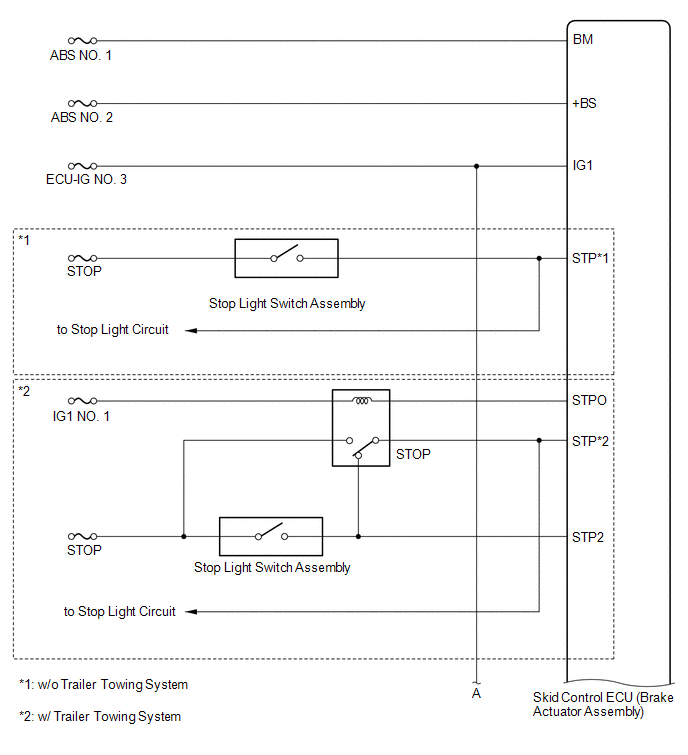
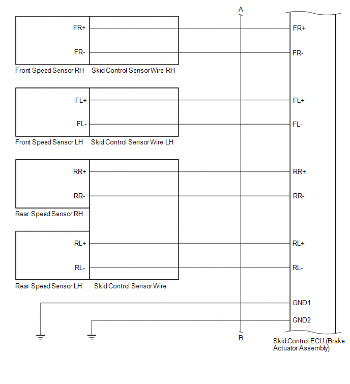
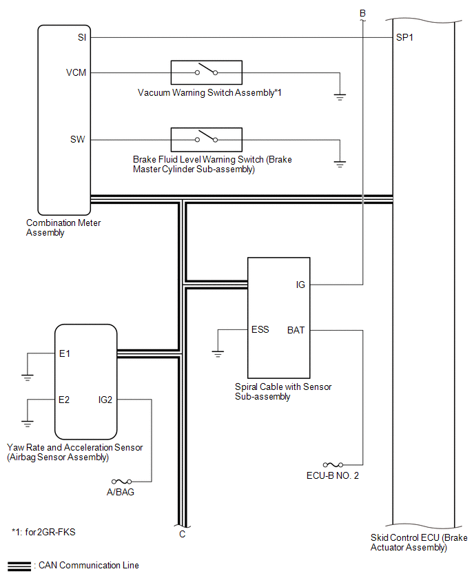
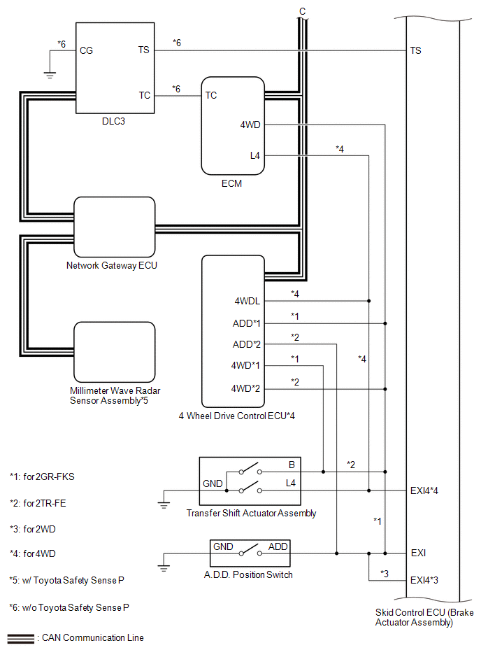
SYSTEM DIAGRAM
|
Transmitting ECU (Transmitter) |
Receiving ECU |
Signal |
Communication Method |
|---|---|---|---|
|
Skid control ECU (Brake actuator assembly) |
Steering angle sensor (Spiral cable with sensor sub-assembly) |
Steering angle sensor request signal |
CAN communication system |
|
Steering angle sensor (Spiral cable with sensor sub-assembly) |
Skid control ECU (Brake actuator assembly) |
Steering angle sensor signal |
CAN communication system |
|
Skid control ECU (Brake actuator assembly) |
Yaw rate and acceleration sensor (Airbag sensor assembly) |
Yaw rate and acceleration request signal |
CAN communication system |
|
Yaw rate and acceleration sensor (Airbag sensor assembly) |
Skid control ECU (Brake actuator assembly) |
Yaw rate and acceleration signal |
CAN communication system |
|
Skid control ECU (Brake actuator assembly) |
ECM |
|
CAN communication system |
|
ECM |
Skid control ECU (Brake actuator assembly) |
|
CAN communication system |
|
Skid control ECU (Brake actuator assembly) |
Combination meter assembly |
|
CAN communication system |
|
Wheel speed signal |
Serial communication |
||
|
4 wheel drive control ECU*3 |
Skid control ECU (Brake actuator assembly) |
|
CAN communication system |
- *1: for 4WD
- *2: w/ Rear Differential Lock
- *3: for 4WD or with Rear Differential Lock
- *4: w/o Toyota Safety Sense P
 System Description
SYSTEM DESCRIPTION
1. FUNCTION DESCRIPTION
(a) ABS (Anti-lock Brake System)
(1) The ABS helps prevent the wheels from locking when the brakes are applied
firmly or when braking on a slippery surf ...
 Check For Intermittent Problems
CHECK FOR INTERMITTENT PROBLEMS
1. CHECK FOR INTERMITTENT PROBLEMS
HINT:
A momentary interruption (open circuit) in the connectors and/or wire harnesses
between the sensors and ECUs can be detect ...
Other materials:
Electronic Circuit Inspection Procedure
ELECTRONIC CIRCUIT INSPECTION PROCEDURE
1. BASIC INSPECTION
(a) WHEN MEASURING RESISTANCE OF ELECTRONIC PARTS
(1) Unless otherwise stated, all resistance measurements should be made at an
ambient temperature of 20°C (68°F). Resistance measurements may be inaccurate if
measured at high tempe ...
Dtc Check / Clear
DTC CHECK / CLEAR
CHECK DTC
(a) Connect the Techstream to the DLC3.
(b) Turn the ignition switch to ON.
(c) Turn the Techstream on.
(d) Enter the following menus: Body Electrical / Pre-Collision 2 / Trouble Codes.
(e) Check for DTCs.
Click here
CLEAR DTC
(a) Connect the Techstream to the ...
Precaution
PRECAUTION
1. EXPRESSIONS OF IGNITION SWITCH
HINT:
The type of ignition switch used on this model differs according to the specifications
of the vehicle. The expressions listed in the table below are used in this section.
Expression
Ignition Switch
(Position)
...
