Toyota Tacoma (2015-2018) Service Manual: Dtc Check / Clear
DTC CHECK / CLEAR
1. SUPPLEMENTAL RESTRAINT SYSTEM DTC CHECK (USING SST CHECK WIRE)
(a) Check the DTCs (Present DTCs).
(1) Turn the ignition switch to ON, and wait for approximately 60 seconds.
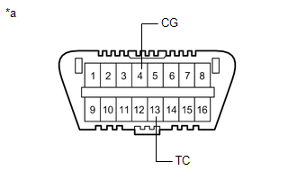
(2) Using SST, connect terminals TC and CG of the DLC3.
SST: 09843-18040
NOTICE:
Connect the terminals to the correct positions to avoid a malfunction.
(b) Check the DTCs (Past DTCs).
(1) Using SST, connect terminals TC and CG of the DLC3.
SST: 09843-18040
NOTICE:
Connect the terminals to the correct positions to avoid a malfunction.
(2) Turn the ignition switch to ON, and wait for approximately 60 seconds.
Text in Illustration|
*a |
DLC3 |
(c) Read the DTCs.
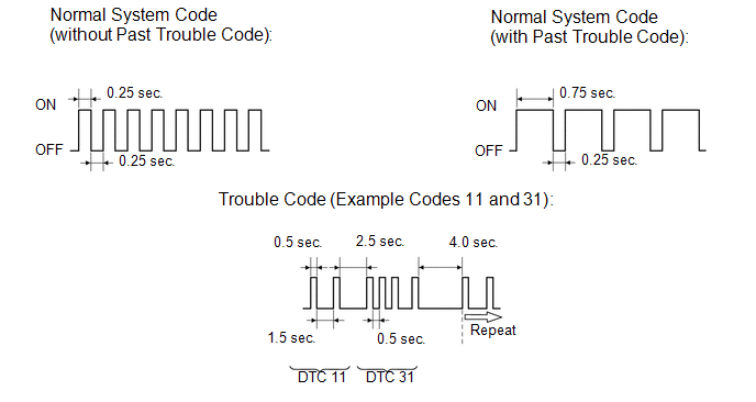
(1) Observe the SRS warning light blinking patterns to read DTCs. As examples, the blinking patterns for the normal system indication, the past DTC indication, and the present DTC indication are shown in the illustration.
- Normal system indication
The SRS warning light blinks twice per second.
- Past DTC indication
When any past DTCs are stored in the airbag sensor assembly, the SRS warning light blinks only once per second.
- Present DTC indication
The first blinking indicates the first digit of a 2-digit DTC. The second blinking occurs after a 1.5-second pause to indicate the second digit.
If there are 2 or more DTCs, there is a 2.5-second pause after each one. After all the DTC are displayed, there is a 4.0-second pause, and they are repeated.
HINT:
- If 2 or more malfunctions are found, the indication begins with the smaller numbered code.
- If DTCs are indicated without connecting the terminals, proceed to "TC
and CG Terminal Circuit" (See page
.gif) ).
).
2. DTC CLEAR (USING SST CHECK WIRE)
(a) Clear the DTCs.
(1) When the ignition switch is turned off (turned to the lock position), the DTCs are cleared.
HINT:
Depending on the DTCs, the DTCs may not be cleared by turning off the ignition switch. In this case, proceed to the next procedure.
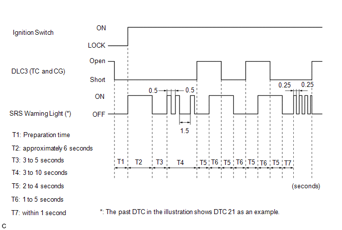
(2) Using SST, connect terminals TC and CG of the DLC3, and then turn the ignition switch to ON.
SST: 09843-18040
(3) Disconnect terminal TC of the DLC3 within 3 to 10 seconds after the DTCs being output, and check if the SRS warning light comes on within 3 seconds.
(4) Within 2 to 4 seconds of the SRS warning light coming on, connect terminals TC and CG of the DLC3.
(5) The SRS warning light should turn off within 2 to 4 seconds after connecting terminals TC and CG of the DLC3. Then, disconnect terminal TC within 2 to 4 seconds after the SRS warning light turning off.
(6) The SRS warning light comes on again within 2 to 4 seconds after disconnecting terminal TC. Then, reconnect terminals TC and CG within 2 to 4 seconds after the SRS warning light coming on, connect terminals TC and CG of the DLC3.
(7) Check if the SRS warning light turns off 2 to 4 seconds after connecting terminals TC and CG of the DLC3. Also check if the normal system indication is displayed within 1 second of the SRS warning light turning off.
If DTCs are not cleared, repeat this procedure until the codes are cleared.
3. SUPPLEMENTAL RESTRAINT SYSTEM DTC CHECK (USING TECHSTREAM)
(a) Check the DTCs.
(1) Connect the Techstream to the DLC3.
(2) Turn the ignition switch to ON and turn the Techstream on.
(3) Check the DTCs by following the prompts on the Techstream screen.
HINT:
Refer to the Techstream operator manual for further details.
(b) Clear the DTCs.
(1) Connect the Techstream to the DLC3.
(2) Turn the ignition switch to ON and turn the Techstream on.
(3) Clear the DTCs by following the prompts on the Techstream screen.
HINT:
Refer to the Techstream operator's manual for further details.
 Diagnosis System
DIAGNOSIS SYSTEM
1. CHECK DLC3
(a) The vehicle ECUs use ISO 15765-4 communication protocol. The terminal arrangement
of the DLC3 complies with ISO 15031-3 and matches the ISO 15765-4 format.
...
 Terminals Of Ecu
TERMINALS OF ECU
1. AIRBAG SENSOR ASSEMBLY
Terminal No.
Terminal Symbol
Destination
A21-1
P2+
Instrument panel passenger wit ...
Other materials:
Inspection
INSPECTION
PROCEDURE
1. INSPECT BRAKE CYLINDER AND PISTON
(a) Check the cylinder bore and piston for rust and scoring.
2. INSPECT PAD LINING THICKNESS
(a) Using a ruler, measure the pad lining thickness.
Standard thickness:
11.5 mm (0.453 in.)
Minimum thickness:
1.0 mm (0.0394 in.) ...
CD cannot be Inserted / Played or CD is Ejected Right After Insertion
PROCEDURE
1.
CHECK IF A PROPER CD IS INSERTED
(a) Make sure that the CD is an audio CD or a CD with an MP3, WMA or AAC file,
and that it is not deformed, flawed, stained, deteriorated or otherwise defective.
OK:
CD is normal.
HINT:
Translucent or uniq ...
Installation
INSTALLATION
CAUTION / NOTICE / HINT
HINT:
Use the same procedures for both the LH and RH sides.
The procedure described below is for the LH side.
PROCEDURE
1. INSTALL OUTER REAR VIEW MIRROR ASSEMBLY
(a) Engage the claw to install the outer rear view mirror assembly.
(b) Ins ...
