Toyota Tacoma (2015-2018) Service Manual: Driver Side Door Entry Lock Function does not Operate
DESCRIPTION
If the entry lock function does not operate for the driver door only, but the entry unlock function operates, the request code is being transmitted properly from the driver door. In this case, there may be a problem related to the front door outside handle assembly LH (lock sensor) (connection between the certification ECU (smart key ECU assembly) and front door outside handle assembly LH [lock sensor]).
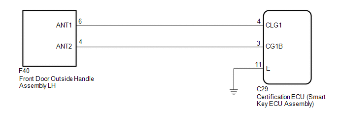
WIRING DIAGRAM
CAUTION / NOTICE / HINT
NOTICE:
- The smart key system (for Entry Function) uses a multiplex communication
system (LIN communication system) and the CAN communication system. Inspect
the communication function by following How to Proceed with Troubleshooting.
Troubleshoot the smart key system (for Entry Function) after confirming
that the communication systems are functioning properly (See page
.gif) ).
). - When using the Techstream with the engine switch off, connect the Techstream to the DLC3 and turn a courtesy light switch on and off at intervals of 1.5 seconds or less until communication between the Techstream and the vehicle begins. Then select the vehicle type under manual mode and enter the following menus: Body Electrical / Smart Key. While using the Techstream, periodically turn a courtesy light switch on and off at intervals of 1.5 seconds or less to maintain communication between the Techstream and the vehicle.
- Check that there are no electrical key transmitter sub-assemblies in the vehicle.
- Before performing the inspection, check that DTC B1242 (wireless door
lock control) is not output (See page ).
- Before replacing the certification ECU (smart key ECU assembly), refer
to the smart key system (for Entry Function) precaution (See page
).
- After repair, confirm that no DTCs are output by performing the "DTC Output Confirmation Operation".
PROCEDURE
|
1. |
CHECK POWER DOOR LOCK CONTROL SYSTEM |
(a) When the door control switch on the power window regulator switch assembly
is operated, check that the doors unlock and lock according to the switch operation
(See page ).
OK:
Door locks operate normally.
| NG | .gif) |
GO TO POWER DOOR LOCK CONTROL SYSTEM |
|
.gif)
|
2. |
READ VALUE USING TECHSTREAM (D-DOOR TRIGGER SWITCH) |
(a) Connect the Techstream to the DLC3.
(b) Turn the engine switch on (IG).
(c) Turn the Techstream on.
(d) Enter the following menus: Body Electrical / Smart Key / Data List.
(e) Read the Data List according to the display on the Techstream.
Smart Key|
Tester Display |
Measurement Item/Range |
Normal Condition |
Diagnostic Note |
|---|---|---|---|
|
D-Door Trigger Switch |
Driver door touch sensor (lock sensor) / ON or OFF |
ON: Driver door touch sensor (lock sensor) touched OFF: Driver door touch sensor (lock sensor) not touched |
|
OK:
The Techstream display changes correctly in response to the operation of the front door outside handle assembly LH.
Result|
Result |
Proceed to |
|---|---|
|
NG |
A |
|
OK |
B |
| B | |
REPLACE CERTIFICATION ECU (SMART KEY ECU ASSEMBLY) |
|
|
3. |
CHECK HARNESS AND CONNECTOR (CERTIFICATION ECU (SMART KEY ECU ASSEMBLY) - FRONT DOOR OUTSIDE HANDLE ASSEMBLY LH) |
(a) Disconnect the C29 certification ECU (smart key ECU assembly) connector.
(b) Disconnect the F40 front door outside handle assembly LH connector.
(c) Measure the resistance according to the value(s) in the table below.
Standard Resistance:
|
Tester Connection |
Condition |
Specified Condition |
|---|---|---|
|
C29-4 (CLG1) - F40-6 (ANT1) |
Always |
Below 1 Ω |
|
C29-3 (CG1B) - F40-4 (ANT2) |
Always |
Below 1 Ω |
|
C29-4 (CLG1) or F40-6 (ANT1) - Body ground |
Always |
10 kΩ or higher |
|
C29-3 (CG1B) or F40-4 (ANT2) - Body ground |
Always |
10 kΩ or higher |
(d) Reconnect the F40 front door outside handle assembly LH connector.
(e) Reconnect the C29 certification ECU (smart key ECU assembly) connector.
| NG | |
REPAIR OR REPLACE HARNESS OR CONNECTOR |
|
|
4. |
CHECK FRONT DOOR OUTSIDE HANDLE ASSEMBLY LH (INPUT TO DRIVER DOOR LOCK SENSOR) |
(a) Using an oscilloscope, check the waveform.
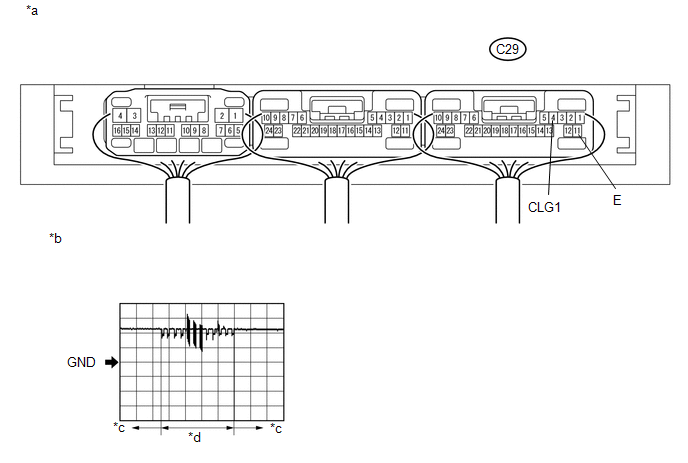 Text in Illustration
|
*a |
Component with harness connected (Certification ECU (smart key ECU assembly)) |
*b |
Waveform 1 |
|
*c |
Lock sensor not touched |
*d |
Lock sensor touched |
OK:
|
Tester Connection |
Switch Condition |
Tool Setting |
Specified Condition |
|---|---|---|---|
|
C29-4 (CLG1) - C29-11 (E) |
Procedure:
|
5 V/DIV., 40 ms/DIV. |
Pulse generation (See waveform 1) |
- *: For details about the entry function detection area, refer to Operation
Check (See page ).
| OK | |
REPLACE CERTIFICATION ECU (SMART KEY ECU ASSEMBLY) |
| NG | |
REPLACE FRONT DOOR OUTSIDE HANDLE ASSEMBLY LH |
 Driver Side Door Entry Unlock Function does not Operate
DESCRIPTION
If the entry unlock function does not operate for the driver door only, but the
entry lock function operates, the request code is being transmitted properly from
the driver door. In t ...
 Entry Interior Alarm does not Sound
DESCRIPTION
The smart key system (for Entry Function) uses the buzzer in the combination
meter assembly to perform various vehicle interior warnings. When the conditions
of each warning are met, ...
Other materials:
Road Test
ROAD TEST
1. PROBLEM SYMPTOM CONFIRMATION
(a) Based on the result of the customer problem analysis, try to reproduce the
symptoms. If the problem is that the transmission does not shift up or down, or
that the shift point is too high or too low, conduct the following road test referring
to t ...
All Doors LOCK/UNLOCK Functions do not Operate Via Door Control Switch or Door
Key Cylinder
DESCRIPTION
The main body ECU (multiplex network body ECU) receives switch signals from the
power window regulator master switch assembly and driver door key cylinder lock
or unlock switch signals from the front door lock assembly. The main body ECU (multiplex
network body ECU) activates the ...
Pressure Control Solenoid "B" Electrical (Shift Solenoid Valve SL2) (P0778)
DESCRIPTION
Changing from 1st to 6th is performed by the ECM turning shift solenoid valves
SL1, SL2, SL3 and SL4 on and off. If an open or short circuit occurs in any of the
shift solenoid valves, the ECM controls the remaining normal shift solenoid valves
to allow the vehicle to be operated ...
