Toyota Tacoma (2015-2018) Service Manual: Disassembly
DISASSEMBLY
PROCEDURE
1. REMOVE FRONT BRAKE SHOE
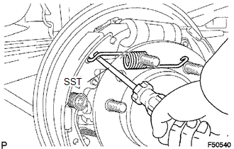
(a) Using SST, remove the shoe return spring from the front brake shoe.
SST: 09921-00010
|
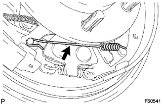
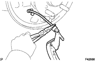
(b) Using needle-nose pliers, remove the return spring. |
|
|
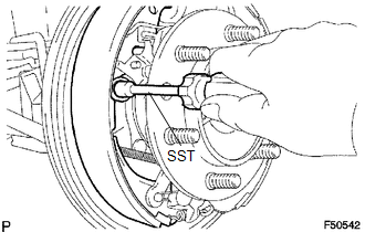
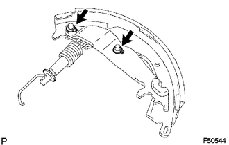
(c) Using SST, remove the shoe hold down spring cup, shoe hold down spring and pin. SST: 09718-00010 |
|
(d) Remove the parking brake shoe strut lower.
(e) Remove the tension spring and front brake shoe.
(f) Remove the automatic adjust lever spring and automatic adjust lever LH from the front brake shoe.
2. REMOVE REAR BRAKE SHOE
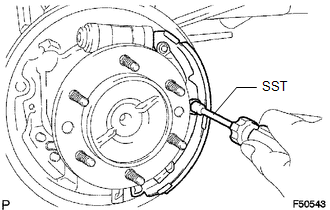
(a) Using SST, remove the shoe hold down spring cup, shoe hold down spring and pin.
SST: 09718-00010
|
(b) Using needle-nose pliers, disconnect the parking brake cable No. 3 and remove the rear brake shoe. |
|
|
(c) Using a screwdriver, remove the 2 C-washers, parking brake shoe lever, parking brake reaction lever and parking brake shoe strut set. |
|
3. REMOVE FRONT OR UPPER REAR WHEEL BRAKE CYLINDER ASSEMBLY
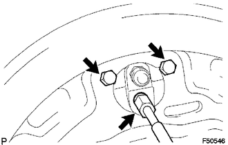
(a) Using a union nut wrench, disconnect the brake tube, and use a container to collect the brake fluid as it flows out.
(b) Remove the 2 bolts and rear wheel brake cylinder assembly.
4. REMOVE REAR WHEEL CYLINDER CUP KIT
(a) Remove the 2 wheel cylinder boots from the rear wheel brake cylinder.
(b) Remove the 2 pistons and compression spring.
(c) Remove the 2 cylinder cups from each piston.
(d) Remove the bleeder plug cap and bleeder plug from the rear wheel brake cylinder.
 Components
COMPONENTS
ILLUSTRATION
...
 Removal
REMOVAL
PROCEDURE
1. REMOVE REAR WHEEL
2. DRAIN BRAKE FLUID
HINT:
Immediately wash off any brake fluid that comes into contact with any painted
surfaces.
3. REMOVE REAR BRAKE DRUM SUB-ASSEMBLY ...
Other materials:
HD Radio Tuner Malfunction (B1551,B15A0,B15AD,B15B0,B15B3,B15B4,B15B7)
DESCRIPTION
These DTCs are stored when a malfunction occurs in the navigation receiver assembly.
DTC No.
DTC Detection Condition
Trouble Area
B1551
When one of the conditions below is met:
"HD Radio" tuner decoder ...
Wheels
If a wheel is bent, cracked or heavily corroded, it should be replaced.
Otherwise, the tire may separate from the wheel or cause loss of handling control.
■ Wheel selection
When replacing wheels, care should be taken to ensure that they are equivalent
to those removed in load capacity, di ...
Precaution
PRECAUTION
1. BASIC REPAIR HINT
(a) HINTS ON OPERATIONS
1
Attire
Always wear a clean uniform.
A hat and safety shoes must be worn.
2
Vehicle protection
Prepare a grille cover, fe ...
