Toyota Tacoma (2015-2018) Service Manual: Components
COMPONENTS
ILLUSTRATION
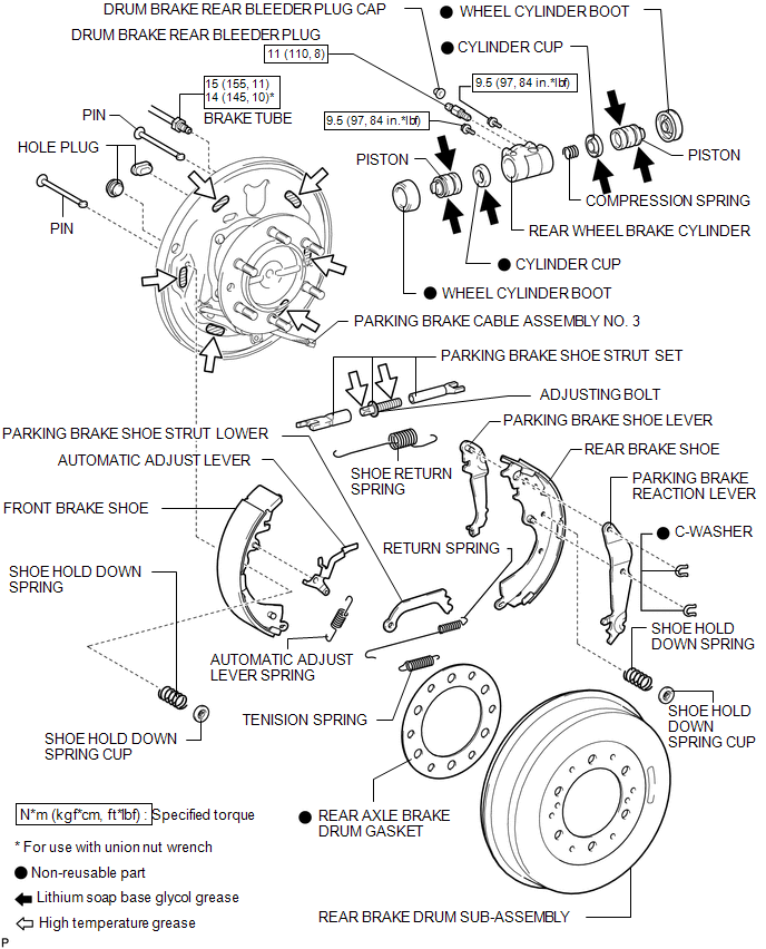
 Rear Brake
...
 Disassembly
DISASSEMBLY
PROCEDURE
1. REMOVE FRONT BRAKE SHOE
(a) Using SST, remove the shoe return spring from the front brake shoe.
SST: 09921-00010
(b) Using needle-nose pliers, remove the ret ...
Other materials:
Rear view monitor system
The rear view monitor system assists the driver by displaying guide lines and
an image of the view behind the vehicle while backing up, for example while parking.
The screen illustrations used in this text are intended as examples, and may
differ from the image that is actually displayed on the ...
Engine Switch Illumination Circuit
DESCRIPTION
The illuminated entry system controls the engine switch illumination.
WIRING DIAGRAM
PROCEDURE
1.
READ VALUE USING TECHSTREAM (POWER/ENGINE SW LIGHT)
(a) Connect the Techstream to the DLC3.
(b) Turn the engine switch to ON.
(c) Turn the Techstream ...
Reassembly
REASSEMBLY
PROCEDURE
1. INSTALL COMPRESSOR PICK UP SENSOR
(a) Install the compressor pick up sensor with the 3 screws.
(b) Engage the clamp.
2. INSTALL MAGNET CLUTCH ASSEMBLY
(a) Secure the cooler compressor assembly in a vise between ...
