Toyota Tacoma (2015-2018) Service Manual: Components
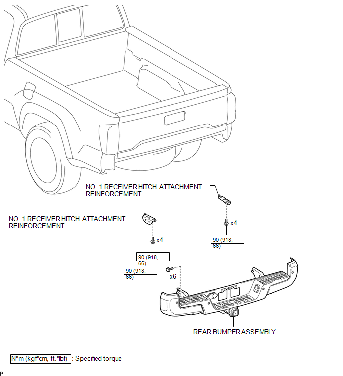
COMPONENTS
ILLUSTRATION
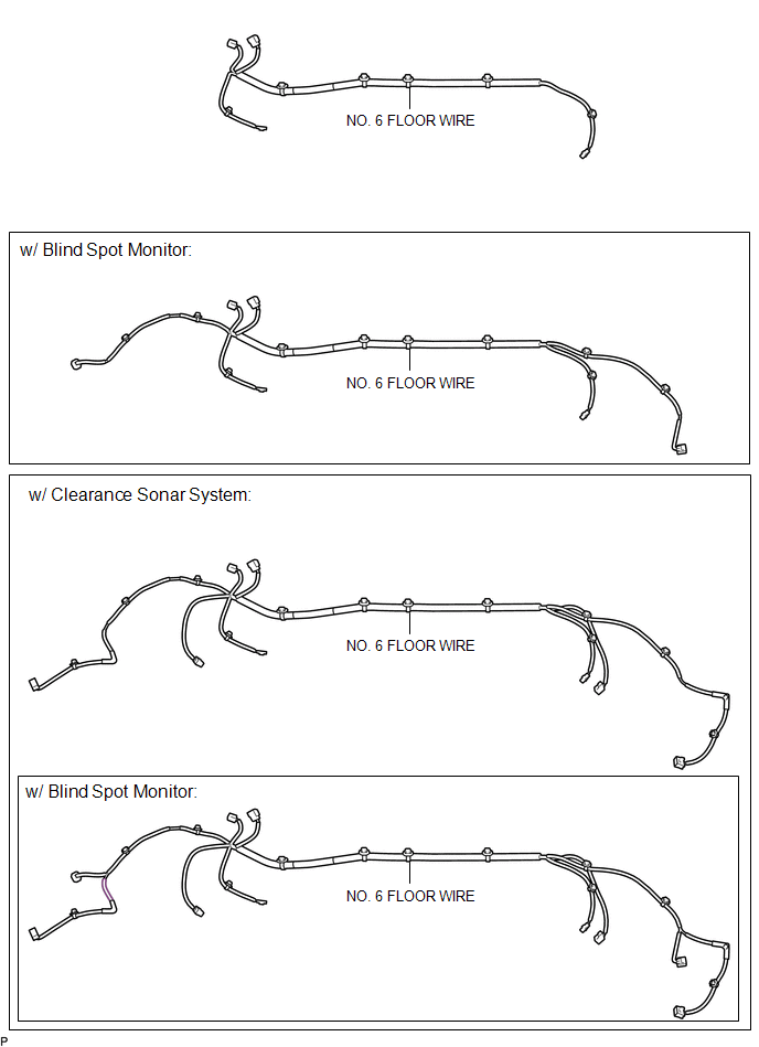
ILLUSTRATION

ILLUSTRATION
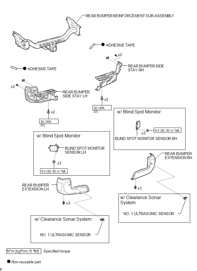
ILLUSTRATION

 Removal
REMOVAL
CAUTION / NOTICE / HINT
HINT:
If the bumper is damaged, there is a possibility that the installation area of
the blind spot monitor sensor may be deformed and the blind spot monitor syste ...
Other materials:
Dtc Combination Table
DTC COMBINATION TABLE
HOW TO INTERPRET COMMUNICATION DTCS (DTCS THAT START WITH U)
(a) If a CAN communication error cannot be reproduced, determine the suspected
malfunctioning part using the DTCs stored in ECUs that are connected to the CAN
buses by following the procedure below.
HINT:
Comm ...
SM Solenoid Circuit (C1225-C1228,C1468,C1469,C146A,C146B)
DESCRIPTION
The solenoid goes on when signals are received from the skid control ECU (master
cylinder solenoid) and controls the pressure action on the wheel cylinders thus
controlling the braking force.
DTC No.
DTC Detecting Conditions
Trouble Areas
...
Installation
INSTALLATION
PROCEDURE
1. INSTALL CLUTCH PEDAL NO.1 CUSHION
(a) Install the clutch pedal No. 1 cushion to the clutch pedal sub-assembly.
2. INSTALL CLUTCH PEDAL SHAFT COLLAR
(a) Apply MP grease to the clutch pedal shaft collar.
Text in Illustration
MP grease
(b) ...
