Toyota Tacoma (2015-2018) Service Manual: Disassembly
DISASSEMBLY
PROCEDURE
1. FIX VANE PUMP
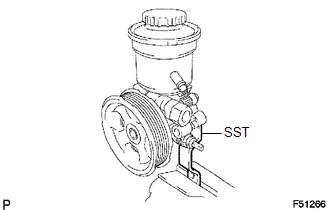
(a) Using SST, fix the vane pump assembly in a vise.
SST: 09630-00014
09631-00132
NOTICE:
When using a vise, do not overtighten it.
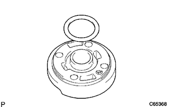
2. REMOVE VANE PUMP OIL RESERVOIR SUB-ASSEMBLY
(a) Remove the 3 bolts and vane pump oil reservoir.
(b) Remove the O-ring from the vane pump oil reservoir.
3. REMOVE FLOW CONTROL VALVE
(a) Remove the pressure port union.
(b) Remove the O-ring from the pressure port union.
(c) Remove the flow control valve and compression spring.
4. REMOVE POWER STEERING OIL PRESSURE SWITCH
NOTICE:
Be careful not to drop or badly damage the oil pressure switch. If damaged, replace it with a new one.
5. REMOVE VANE PUMP HOUSING REAR
(a) Remove the 4 bolts and vane pump housing rear from the vane pump housing front.
(b) Remove the O-ring from the vane pump housing front.
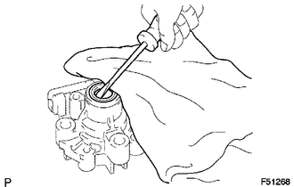
6. REMOVE PULLEY SHAFT SUB-ASSEMBLY
NOTICE:
Be careful not to drop or badly damage the pulley shaft. If damaged, replace it with a new one.
(a) Using a screwdriver, remove the snap ring from the pulley shaft.
(b) Remove the pulley shaft.
7. REMOVE VANE PUMP ROTOR
(a) Remove the 10 vane plates.
(b) Remove the vane pump rotor.
8. REMOVE VANE PUMP CAM RING
9. REMOVE VANE PUMP SIDE PLATE FRONT
(a) Remove the side plate from the vane pump housing front.
(b) Remove the O-ring from the side plate.
|
(c) Remove the O-ring from the vane pump housing front. |
|
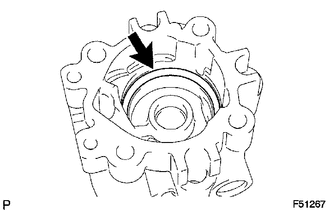
10. REMOVE VANE PUMP HOUSING OIL SEAL
(a) Using screwdriver, remove the oil seal.
NOTICE:
Be careful not to damage the vane pump housing front.
 Components
COMPONENTS
ILLUSTRATION
ILLUSTRATION
...
 Removal
REMOVAL
PROCEDURE
1. PRECAUTION
NOTICE:
After turning the ignition switch off, waiting time may be required before disconnecting
the cable from the negative (-) battery terminal.
Therefore, mak ...
Other materials:
Data List / Active Test
DATA LIST / ACTIVE TEST
HINT:
By accessing the Data List displayed by the Techstream, you can check values
of switches and sensors without removing any parts. Reading the Data List as the
first step of troubleshooting is one method to shorten diagnostic time.
1. DATA LIST FOR OCCUPANT DETECTI ...
Components
COMPONENTS
ILLUSTRATION
*A
w/ Rear Seat Assembly
*B
w/o Rear Seat Assembly
*1
BACK PANEL GARNISH HOLE PLUG
*2
BACK PANEL TRIM
*3
NO. 3 ROOM PARTITION COVER
*4
...
Some Alarm Functions do not Operate
DESCRIPTION
When the alarm sounds, the following alarm functions operate: the roof console
box assembly and No. 1 room light assembly illuminates, and the headlights, taillights
and hazard lights flash, and the security horn and vehicle horn sound intermittently.
WIRING DIAGRAM
CAUTION / ...
