Toyota Tacoma (2015-2018) Service Manual: Components
COMPONENTS
ILLUSTRATION
|
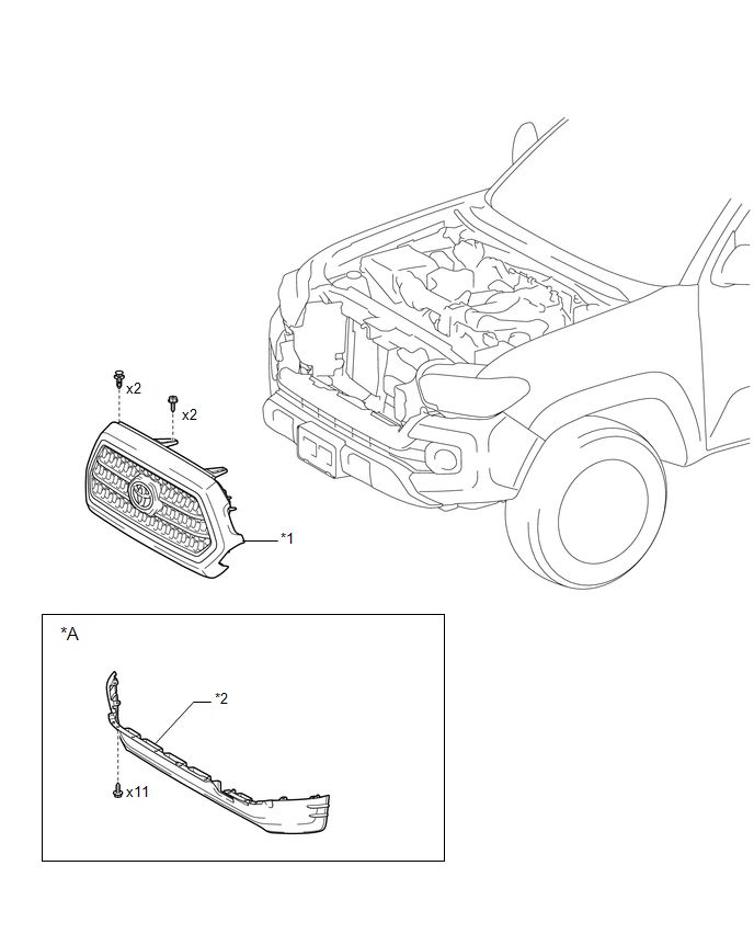
*A |
w/ Front Spoiler |
- |
- |
|
*1 |
RADIATOR GRILLE |
*2 |
FRONT NO. 1 WHEEL OPENING EXTENSION PAD |
ILLUSTRATION
|
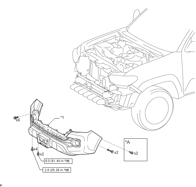
*A |
w/o Over Fender |
- |
- |
|
*1 |
FRONT BUMPER ASSEMBLY |
- |
- |
.png) |
N*m (kgf*cm, ft.*lbf): Specified torque |
- |
- |
ILLUSTRATION
|
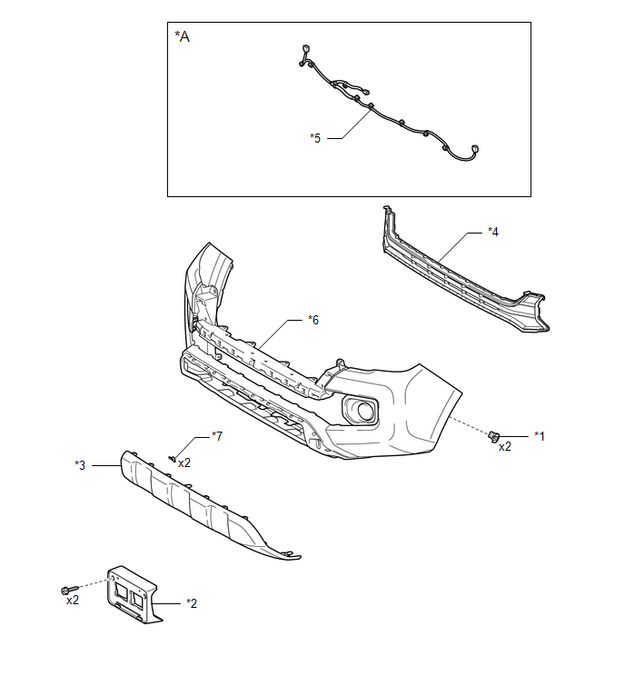
*A |
w/ Fog Light |
- |
- |
|
*1 |
FRONT FENDER LINER RETAINER |
*2 |
FRONT LICENSE PLATE BRACKET |
|
*3 |
FRONT VALANCE PANEL |
*4 |
LOWER NO. 1 RADIATOR GRILLE |
|
*5 |
NO. 4 ENGINE ROOM WIRE |
*6 |
FRONT BUMPER COVER |
|
*7 |
OUTSIDE MOULDING RETAINERS |
- |
- |
ILLUSTRATION
|
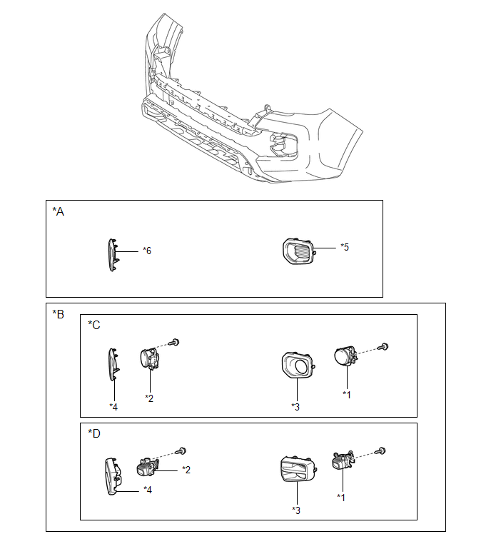
*A |
w/o Fog Light |
*B |
w/ Fog Light |
|
*C |
for Halogen Fog Light |
*D |
for LED Fog Light |
|
*1 |
FOG LIGHT ASSEMBLY LH |
*2 |
FOG LIGHT ASSEMBLY RH |
|
*3 |
FOG LIGHT COVER LH |
*4 |
FOG LIGHT COVER RH |
|
*5 |
FRONT BUMPER HOLE COVER LH |
*6 |
FRONT BUMPER HOLE COVER RH |
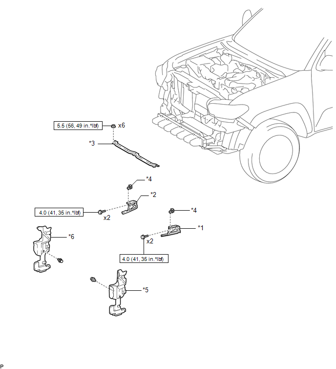
ILLUSTRATION
|
*1 |
FRONT BUMPER ARM MOUNTING BRACKET LH |
*2 |
FRONT BUMPER ARM MOUNTING BRACKET RH |
|
*3 |
FRONT BUMPER UPPER CENTER RETAINER |
*4 |
HEADLIGHT MOUNTING BRACKET |
|
*5 |
RADIATOR SIDE DEFLECTOR LH |
*6 |
RADIATOR SIDE DEFLECTOR RH |
|
|
N*m (kgf*cm, ft.*lbf): Specified torque |
- |
- |
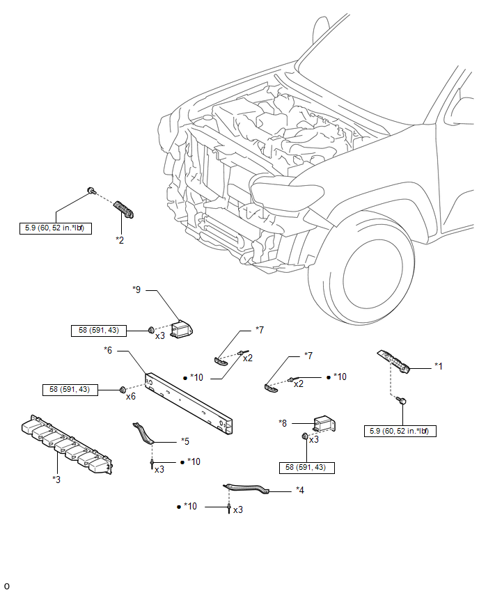
ILLUSTRATION
|
*1 |
FRONT BUMPER COVER INSERT LH |
*2 |
FRONT BUMPER COVER INSERT RH |
|
*3 |
FRONT BUMPER ENERGY ABSORBER |
*4 |
FRONT BUMPER INNER ARM SUB-ASSEMBLY LH |
|
*5 |
FRONT BUMPER INNER ARM SUB-ASSEMBLY RH |
*6 |
FRONT BUMPER REINFORCEMENT |
|
*7 |
LOWER FRONT BUMPER RETAINER |
*8 |
NO. 2 FRONT BUMPER EXTENSION SUB-ASSEMBLY LH |
|
*9 |
NO. 2 FRONT BUMPER EXTENSION SUB-ASSEMBLY RH |
*10 |
RIVET |
|
|
N*m (kgf*cm, ft.*lbf): Specified torque |
â—Ź |
Non-reusable part |
 Front Bumper
...
 Disassembly
DISASSEMBLY
PROCEDURE
1. REMOVE FRONT LICENSE PLATE BRACKET
(a) Remove the 2 screws and front license plate bracket.
2. REMOVE NO. 4 ENGINE ROO ...
Other materials:
Slip Indicator Light does not Come ON
DESCRIPTION
Refer to Slip Indicator Light Remains ON (See page
).
WIRING DIAGRAM
Refer to Slip Indicator Light Remains ON (See page
).
CAUTION / NOTICE / HINT
NOTICE:
When replacing the skid control ECU (brake actuator assembly), perform zero point
calibration and store system informatio ...
Hydraulic Test
HYDRAULIC TEST
1. PERFORM HYDRAULIC TEST
(a) Measure the line pressure.
CAUTION:
The line pressure test should always be performed with at least 2 people. One
person should observe the condition of the wheels and wheel chocks while the other
is performing the test.
NOTICE:
Perform ...
Navigation Receiver
Components
COMPONENTS
ILLUSTRATION
ILLUSTRATION
Removal
REMOVAL
PROCEDURE
1. REMOVE INSTRUMENT CLUSTER CENTER FINISH PANEL SUB-ASSEMBLY
(See page )
2. REMOVE NAVIGATION RECEIVER ASSEMBLY WITH BRACKET
(a) Remove the 4 bolts.
(b ...
