Toyota Tacoma (2015-2018) Service Manual: Components
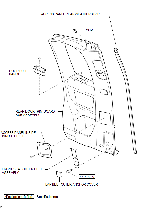
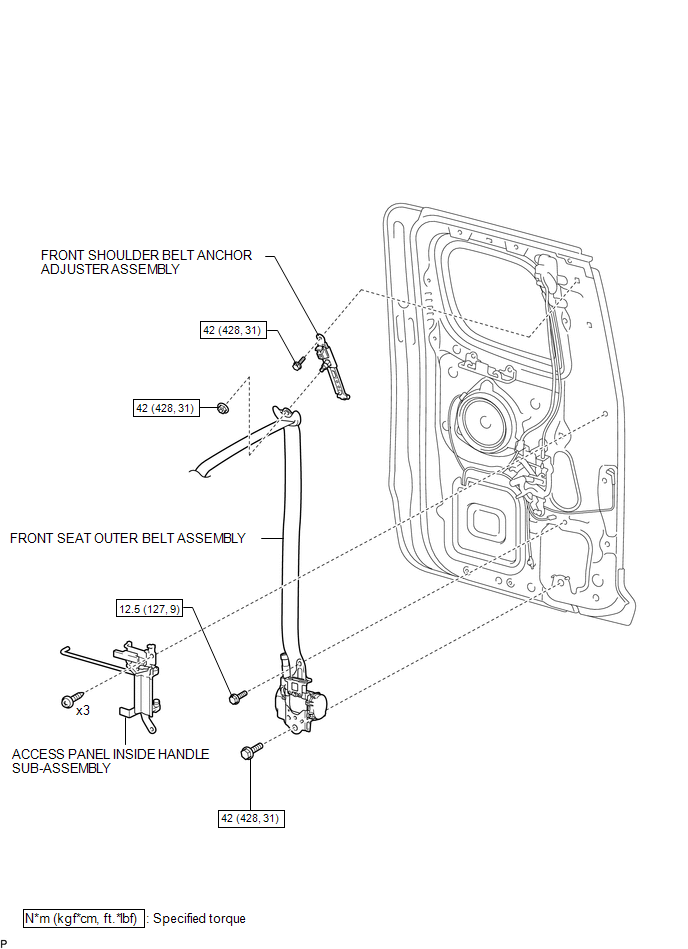
COMPONENTS
ILLUSTRATION
ILLUSTRATION

 Installation
INSTALLATION
CAUTION / NOTICE / HINT
HINT:
Use the same procedure for both the RH and LH sides.
The procedure described below is for the LH side.
PROCEDURE
1. INSTALL FRONT SHOU ...
Other materials:
Diagnostic Trouble Code Chart
DIAGNOSTIC TROUBLE CODE CHART
NOTICE:
When removing any parts, turn the ignition switch off.
HINT:
If no abnormality is found when inspecting parts, check the skid control
ECU and check for poor contact at ground points.
When 2 or more DTCs are detected, perform each circuit insp ...
Problem Symptoms Table
PROBLEM SYMPTOMS TABLE
HINT:
Use the table below to help determine the cause of problem symptoms.
If multiple suspected areas are listed, the potential causes of the symptoms
are listed in order of probability in the "Suspected Area" column of the
table. Check each sy ...
Reassembly
REASSEMBLY
CAUTION / NOTICE / HINT
CAUTION:
Wear protective gloves. Sharp areas on the parts may injure your hands.
PROCEDURE
1. INSTALL SEPARATE TYPE REAR SEATBACK COVER
(a) Using hog ring pliers, install the separate type rear seatback cover
with 2 new hog rings.
Text in Il ...
