Toyota Tacoma (2015-2018) Service Manual: Removal
REMOVAL
PROCEDURE
1. PRECAUTION
CAUTION:
Be sure to read Precaution thoroughly before servicing (See page
.gif) ).
).
NOTICE:
After turning the ignition switch off, waiting time may be required before disconnecting the cable from the negative (-) battery terminal. Therefore, make sure to read the disconnecting the cable from the negative (-) battery terminal notices before proceeding with work.
Click here
2. DISCONNECT CABLE FROM NEGATIVE BATTERY TERMINAL
CAUTION:
Wait at least 90 seconds after disconnecting the cable from the negative (-) battery terminal to disable the SRS system.
NOTICE:
When disconnecting the cable, some systems need to be initialized after the cable is reconnected.
Click here
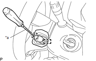
3. REMOVE LOWER NO. 3 STEERING WHEEL COVER
|
(a) Using a screwdriver with its tip wrapped in protective tape, disengage the claw and guide to remove the lower No. 3 steering wheel cover. Text in Illustration
|
|

4. REMOVE LOWER NO. 2 STEERING WHEEL COVER
|
(a) Using a screwdriver with its tip wrapped in protective tape, disengage the claw and guide to remove the lower No. 2 steering wheel cover. Text in Illustration
|
|
5. REMOVE STEERING PAD
CAUTION:
When storing the steering pad, keep the airbag deployment side facing upward.
(a) Check that the ignition switch is off.
(b) Check that the cable is disconnected from the negative (-) battery terminal.
NOTICE:
Wait at least 90 seconds after disconnecting the cable from the negative (-) battery terminal to disable the SRS system.
|
(c) Using a T30 "TORX" socket wrench, loosen the 2 screws until the groove along the screw circumference catches on the screw case. |
|
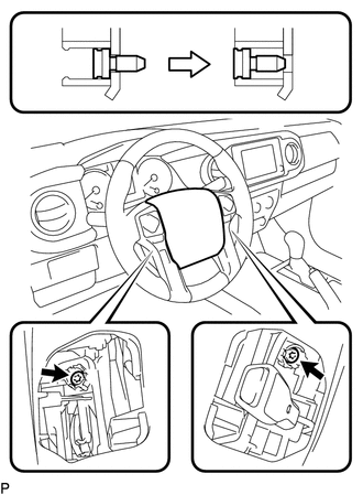
(d) Pull the steering pad toward you.
|
(e) Using a screwdriver with its tip wrapped in protective tape, release the 2 airbag connector locks. Text in Illustration
|
|
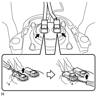
(f) Disconnect the 2 airbag connectors.
NOTICE:
When disconnecting any airbag connector, take care not to damage the airbag wire harness.
(g) Disconnect the horn terminal to remove the steering pad.
 On-vehicle Inspection
ON-VEHICLE INSPECTION
PROCEDURE
1. INSPECT STEERING PAD (for Vehicle not Involved in Collision)
(a) Perform a diagnostic system check (See page
).
(b) With the steering pad installed on the vehi ...
 Installation
INSTALLATION
PROCEDURE
1. INSTALL STEERING PAD
(a) Check that the ignition switch is off.
(b) Check that the cable is disconnected from the negative (-) battery terminal.
CAUTION:
Wait at least ...
Other materials:
Terminals Of Ecu
TERMINALS OF ECU
CHECK MILLIMETER WAVE RADAR SENSOR ASSEMBLY
(a) Measure the voltage and resistance according to the value(s) in the table
below.
Terminal No. (Symbol)
Wiring Color
Terminal Description
Condition
Specified Condition
...
Low Output Signal of Rear Speed Sensor RH (Test Mode DTC) (C1273,C1274,C1403,C1404)
DESCRIPTION
Refer to DTCs C1401 and C1402 (See page ).
DTC Code
DTC Detection Condition
Trouble Area
C1273
C1274
Stored only during test mode.
Rear speed sensor RH/LH
Rear speed sensor rotor RH/LH (rear ax ...
Data Signal Circuit between Radio Receiver and Extension Module
DESCRIPTION
The stereo component tuner assembly sends the image data signal to the radio
and display receiver assembly via this circuit.
WIRING DIAGRAM
PROCEDURE
1.
CHECK NO. 1 NAVIGATION WIRE
(a) Disconnect the R33 radio and display receiver assembly connect ...
