Toyota Tacoma (2015-2018) Service Manual: Removal
REMOVAL
CAUTION / NOTICE / HINT
HINT:
If the bumper is damaged, there is a possibility that the installation area of the blind spot monitor sensor may be deformed and the blind spot monitor system may not operate correctly, so visually inspect the blind spot monitor sensor installation area (frame, stud bolt) to make sure it is not dented or bent.
Click here .gif)
If the visual inspection finds a problem, check the installation condition of the blind spot monitor sensor, and adjust the installation position of the blind spot monitor sensor as necessary.
PROCEDURE
1. REMOVE NO. 1 RECEIVER HITCH ATTACHMENT REINFORCEMENT
|
(a) Remove the 8 bolts. |
|
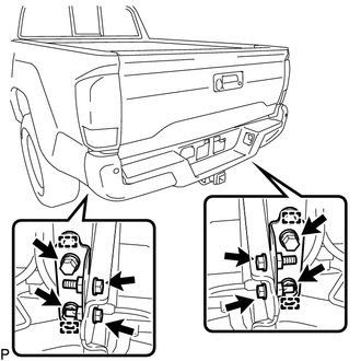
(b) Disengage the 4 guides to remove the 2 No. 1 receiver hitch attachment reinforcements.
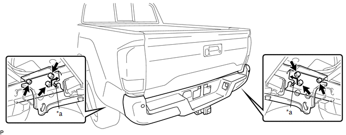
2. REMOVE REAR BUMPER ASSEMBLY
|
(a) Disconnect the 3 connectors. |
|

(b) Using an engine lifter or equivalent, remove the 6 bolts.
 Text in Illustration
|
*a |
Pin |
- |
- |
(c) Disengage the 2 pins to remove the rear bumper assembly as shown in the illustration.
NOTICE:
- Using plate lift attachments or equivalent, set the rear bumper assembly on a flat surface.
- Be sure to perform the operation with 2 persons or more.
- Be careful not to damage the rear bumper assembly.
 Components
COMPONENTS
ILLUSTRATION
ILLUSTRATION
ILLUSTRATION
ILLUSTRATION
...
 Disassembly
DISASSEMBLY
PROCEDURE
1. REMOVE CONNECTOR COVER
(a) Disengage the 2 clips to remove the connector cover.
2. REMOVE REAR BUMPER PAD SUB-ASSEMBLY ...
Other materials:
Installation
INSTALLATION
PROCEDURE
1. ADJUST COMPRESSOR OIL
(a) for HFC-134a (R134a):
(1) When replacing the compressor and magnetic clutch with new ones, after gradually
discharging the refrigerant gas from the service valve, drain the following volume
of oil from new compressor and magnetic clutch bef ...
Removal
REMOVAL
PROCEDURE
1. REMOVE FRONT SEAT ASSEMBLY (for Driver Side)
(See page
)
2. REMOVE FRONT SEAT ASSEMBLY (for Front Passenger Side)
(See page
)
3. REMOVE SEPARATE TYPE FRONT SEATBACK COVER (for Driver Side)
(See page
)
4. REMOVE SEPARATE TYPE FRONT SEATBACK COVER (for Front Pa ...
Diagnosis System
DIAGNOSIS SYSTEM
1. DESCRIPTION
(a) Sliding roof system data and Diagnostic Trouble Codes (DTCs) can be read
through the vehicle Data Link Connector 3 (DLC3). When the system seems to be malfunctioning,
use the Techstream to check for malfunctions and perform repairs.
2. CHECK DLC3
(a) Check ...
