Toyota Tacoma (2015-2018) Service Manual: Components
COMPONENTS
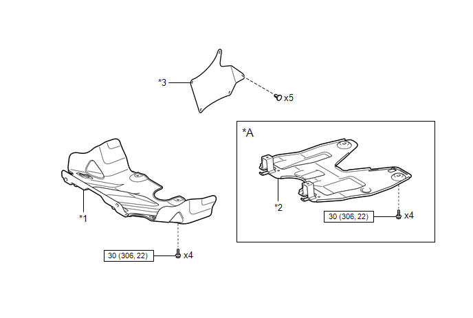
ILLUSTRATION
|
*A |
w/ Off Road Package |
- |
- |
|
*1 |
NO. 1 ENGINE UNDER COVER SUB-ASSEMBLY |
*2 |
NO. 2 ENGINE UNDER COVER SUB-ASSEMBLY |
|
*3 |
FRONT UPPER FENDER APRON SEAL |
- |
- |
.png) |
N*m (kgf*cm, ft.*lbf): Specified torque |
- |
- |
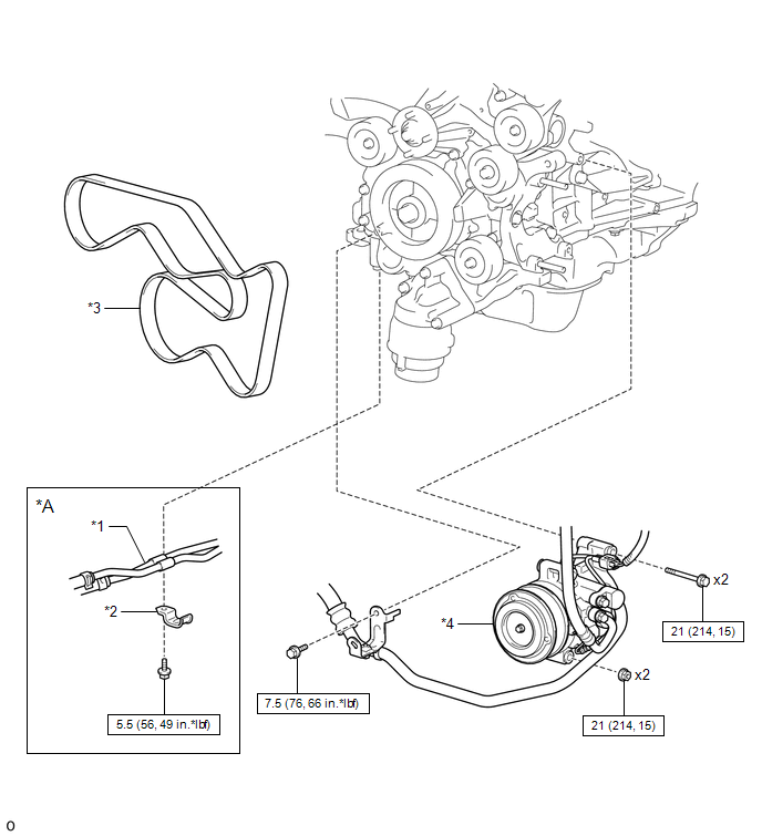
ILLUSTRATION
|
*A |
for Automatic Transmission |
- |
- |
|
*1 |
AUTOMATIC TRANSMISSION OIL COOLER TUBE |
*2 |
CLAMP |
|
*3 |
FAN AND GENERATOR V BELT |
*4 |
COOLER COMPRESSOR ASSEMBLY |
|
|
N*m (kgf*cm, ft.*lbf): Specified torque |
- |
- |
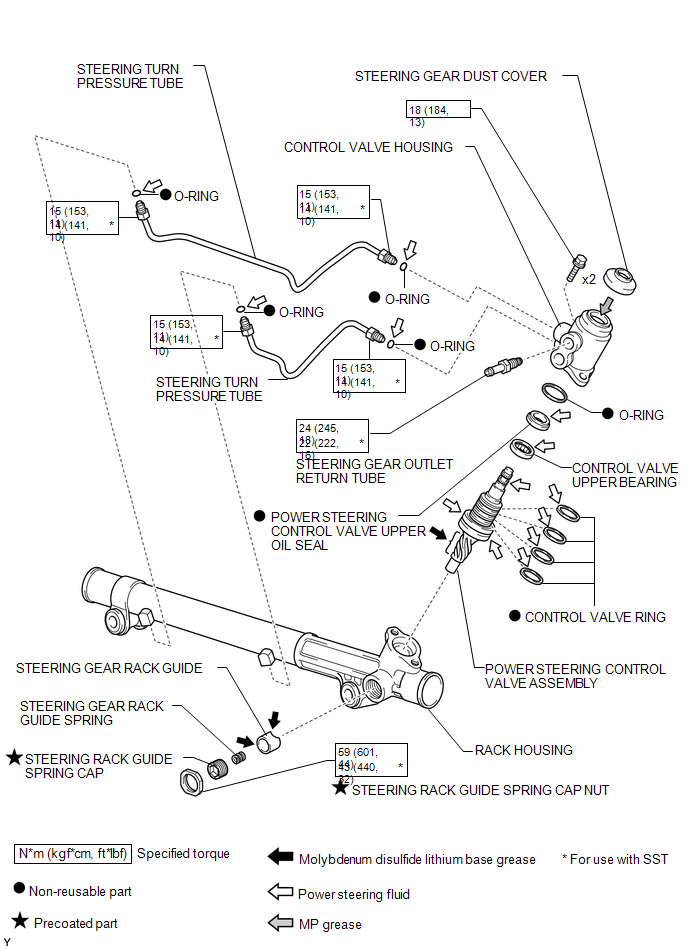
ILLUSTRATION

|
*1 |
POWER STEERING LINK |
*2 |
STEERING SLIDING YOKE |
|
*3 |
NO. 2 STEERING INTERMEDIATE SHAFT |
*4 |
PRESSURE FEED TUBE |
|
*5 |
RETURN HOSE |
*6 |
COTTER PIN |
|
|
N*m (kgf*cm, ft.*lbf): Specified torque |
* |
For use with SST or a union nut wrench |
|
â—Ź |
Non-reusable part |
- |
- |
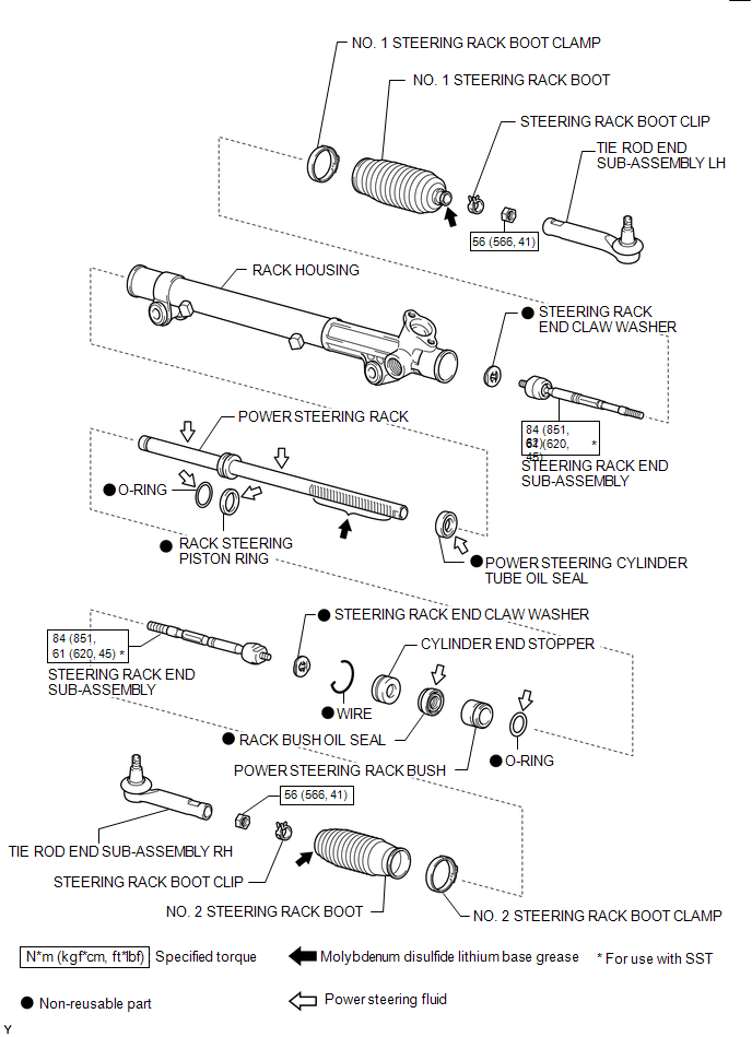
ILLUSTRATION
ILLUSTRATION

 Removal
REMOVAL
PROCEDURE
1. PLACE FRONT WHEELS FACING STRAIGHT AHEAD
2. REMOVE FRONT WHEELS
3. REMOVE FRONT UPPER FENDER APRON SEAL
Click here
4. REMOVE NO. 2 ENGINE UNDER COVER SUB-ASSEMBLY (w/ Of ...
Other materials:
Components
COMPONENTS
ILLUSTRATION
*1
FUEL PUMP ASSEMBLY
*2
FUEL PUMP LIFTER ASSEMBLY
*3
FUEL PUMP LIFTER GUIDE
*4
FUEL PUMP SPACER GASKET
*5
NO. 1 FUEL PIPE SUB-ASSEMBLY
*6
...
Terminals Of Ecu
TERMINALS OF ECU
1. ECM
Terminal No. (Symbol)
Wiring Color
Terminal Description
Condition
Specified Condition
E14-20 (TC) - E11-1 (E1)
G - W-B
DTC output signal
Ignition switch ON
...
Removal
REMOVAL
PROCEDURE
1. REMOVE TIMING CHAIN COVER ASSEMBLY
(See page )
2. SEPARATE NO. 2 WATER BY-PASS PIPE (for Vacuum Brake Booster)
3. REMOVE VACUUM PUMP ASSEMBLY (for Vacuum Brake Booster)
4. SET NO. 1 CYLINDER TO TDC/COMPRESSION
5. REMOVE NO. 1 CHAIN TENSIONER ASSEMBLY
6. REMO ...
