Toyota Tacoma (2015-2018) Service Manual: Removal
REMOVAL
PROCEDURE
1. PLACE FRONT WHEELS FACING STRAIGHT AHEAD
2. REMOVE FRONT WHEELS
3. REMOVE FRONT UPPER FENDER APRON SEAL
Click here .gif)
4. REMOVE NO. 2 ENGINE UNDER COVER SUB-ASSEMBLY (w/ Off Road Package)
5. REMOVE NO. 1 ENGINE UNDER COVER SUB-ASSEMBLY
6. REMOVE FRONT DIFFERENTIAL CARRIER ASSEMBLY (for 4WD)
Click here
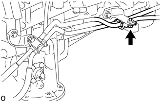
7. SEPARATE AUTOMATIC TRANSMISSION OIL COOLER TUBE (for Automatic Transmission)
HINT:
This procedure is performed to make space for removing and installing the power steering link installation bolt.
|
(a) Remove the bolt and clamp to separate the automatic transmission oil cooler tube. |
|
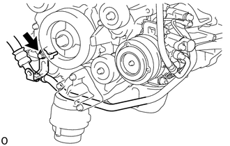
8. SEPARATE COOLER COMPRESSOR ASSEMBLY
HINT:
This procedure is performed to make space for removing and installing the power steering link installation bolt.
(a) Remove the fan and generator V belt.
Click here
|
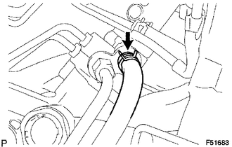
(b) Remove the bolt to separate the suction hose sub-assembly. |
|
(c) Remove the 2 bolts and 2 nuts, and separate the cooler compressor assembly in the direction shown in the illustration.
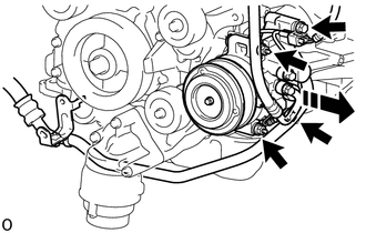
.png) |
Separate in this Direction |
9. REMOVE NO. 2 STEERING INTERMEDIATE SHAFT
|
(a) Fix the steering wheel with the seat belt in order to prevent it from rotating. HINT: The operation is effective for preventing any damage to the spiral cable. |
|
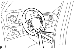
|
(b) Put matchmarks on the steering sliding yoke, No. 2 steering intermediate shaft and steering intermediate shaft. |
|
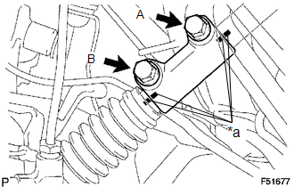
(c) Remove bolts A and B from the steering sliding yoke.
(d) Slide the steering sliding yoke up and separate it from the No. 2 steering intermediate shaft.
(e) Pull down the steering sliding yoke from the steering intermediate shaft to remove it.
|
(f) Put matchmarks on the No. 2 steering intermediate shaft and power steering link. |
|
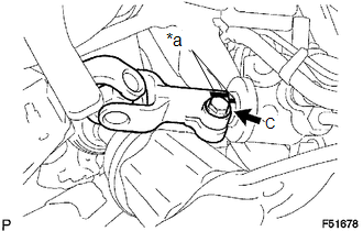
(g) Remove bolt C from the No. 2 steering intermediate shaft.
(h) Slide the No. 2 steering intermediate shaft up and remove it from the power steering link.
10. SEPARATE TIE ROD END SUB-ASSEMBLY LH
Click here
11. SEPARATE TIE ROD END SUB-ASSEMBLY RH
HINT:
Use the same procedures described for the LH side.
12. DISCONNECT PRESSURE FEED TUBE ASSEMBLY
|
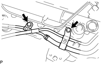
(a) Remove the 2 bolts to separate the tube support brackets. |
|
|
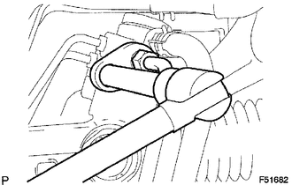
(b) Using a 17 mm union nut wrench, disconnect the pressure feed tube. NOTICE: Do not damage the pressure feed tube. |
|
|
(c) Slide the clip and disconnect the return hose. |
|
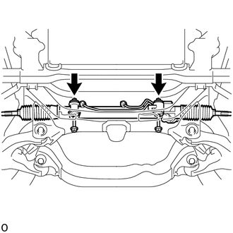
13. REMOVE POWER STEERING LINK
|
(a) Remove the 2 bolts and 2 nuts. NOTICE: While holding the nut in place, loosen the bolt. |
|
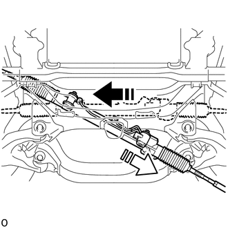
(b) Pull the power steering link out of the vehicle in the order shown in the illustration.
|
|
Remove in this Direction (1) |
 |
Remove in this Direction (2) |
 Components
COMPONENTS
ILLUSTRATION
*A
w/ Off Road Package
-
-
*1
NO. 1 ENGINE UNDER COVER SUB-ASSEMBLY
*2
NO. 2 E ...
 Disassembly
DISASSEMBLY
PROCEDURE
1. REMOVE STEERING GEAR OUTLET RETURN TUBE
(a) Using a union nut wrench, remove the steering gear outlet return tube.
2. REMOVE STEERING TURN PRESSURE TUBE
(a) Using a u ...
Other materials:
Front Camera Module Communication Stop Mode
DESCRIPTION
Detection Item
Symptom
Trouble Area
Front Camera Module Communication Stop Mode
Either Condition is met:
Communication stop for "Front Camera Module" is indicated on
the "Communication Bus Ch ...
Diagnosis System
DIAGNOSIS SYSTEM
1. DESCRIPTION
The main body ECU (multiplex network body ECU) and certification ECU (smart key
ECU assembly) control the LIN communication system. LIN communication system data
and Diagnostic Trouble Codes (DTCs) can be read through the Data Link Connector
3 (DLC3).
When th ...
Cooling System
On-vehicle Inspection
ON-VEHICLE INSPECTION
PROCEDURE
1. INSPECT FOR COOLANT LEAK
CAUTION:
Do not remove the radiator cap sub-assembly, cylinder block drain cock plug or
radiator drain cock plug while the engine and radiator assembly are still hot. Pressurized,
hot engine coolant and stea ...
