Toyota Tacoma (2015-2018) Service Manual: Brake
General Maintenance
GENERAL MAINTENANCE
PROCEDURE
1. INSPECT BRAKE LINE PIPES AND HOSES
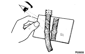
HINT:
Work in a well-lighted area. Turn the front wheels fully to the right or left before beginning.
(a) Check all the brake lines and hoses for:
- Damage
- Wear
- Deformation
- Cracks
- Corrosion
- Leaks
- Bends
- Twists
(b) Check all the clamps for tightness and the connections for leakage.
(c) Check if the hoses and lines are not near sharp edges, moving parts and the exhaust system.
(d) Check if the lines are installed pass through the center of the grommets.
2. INSPECT FRONT BRAKE PADS AND DISCS
HINT:
- (See page
.gif) )
) - If a squealing or scraping noise is heard from the brake while driving, check the pad wear indicator.
- If there are traces of the indicator contacting the disc rotor, the disc pad should be replaced.
3. INSPECT REAR BRAKE DRUM
HINT:
See page
4. INSPECT BRAKE FLUID
Fluid:
SAE J1703 or FMVSS No. 116 DOT3
HINT:
- for Hydraulic Brake Booster (See page
)
- for Vacuum Brake Booster (See page )
 Body
Body
General Maintenance
GENERAL MAINTENANCE
PROCEDURE
1. TIGHTEN BOLTS AND NUTS ON CHASSIS AND BODY
(a) Tighten the bolts and nuts on the chassis parts listed below, if necessary.
Front axle ...
 Chassis
General Maintenance
GENERAL MAINTENANCE
PROCEDURE
1. INSPECT STEERING LINKAGE
(a) Check the steering wheel free play (See page
).
(b) Check the steering linkage for looseness or damage.
(1) ...
Other materials:
Diagnosis System
DIAGNOSIS SYSTEM
1. CHECK DLC3
(a) Check the DLC3 (See page ).
2. INSPECT BATTERY VOLTAGE
(a) Measure the battery voltage.
Standard Voltage:
11 to 14 V
If the voltage is below 11 V, recharge or replace the battery.
3. SELF-DIAGNOSTIC MODE (OPERATING IGNITION KEY CYLINDER)
(a) Switch to se ...
Installation
INSTALLATION
PROCEDURE
1. INSTALL PROPELLER SHAFT WITH CENTER BEARING ASSEMBLY
(a) Remove SST from the extension housing.
(b) Install the propeller shaft to the extension housing.
(c) Completely remove any oil or the like and clean the contact surfaces of the
propeller shaft flange and diff ...
Installation
INSTALLATION
CAUTION / NOTICE / HINT
HINT:
Use the same procedure for both the RH and LH sides.
The procedure described below is for the LH side.
PROCEDURE
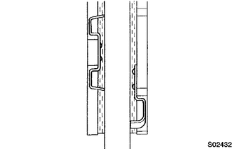
1. INSTALL FRONT SHOULDER BELT ANCHOR ADJUSTER ASSEMBLY
(a) As shown in the illustration, engage the 2 guides ...
