Toyota Tacoma (2015-2018) Service Manual: AV Signal Stoppage (Low Battery Voltage) (B158F)
DESCRIPTION
This DTC is stored when a video or audio signal is interrupted due to battery voltage input to the radio and display receiver assembly dropping temporarily.
|
DTC Code |
DTC Detection Condition |
Trouble Area |
|---|---|---|
|
B158F |
A video or audio signal is interrupted when the battery voltage drops. |
|
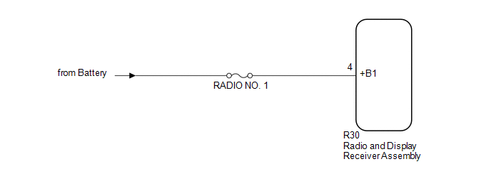
WIRING DIAGRAM
CAUTION / NOTICE / HINT
NOTICE:
Inspect the fuses for circuits related to this system before performing the following procedure.
PROCEDURE
|
1. |
CHECK VEHICLE SIGNAL (OPERATION CHECK) |
|
(a) Enter the "Vehicle Signal Check Mode" screen. Refer to Check Vehicle
Signal in Operation Check (See page |
|
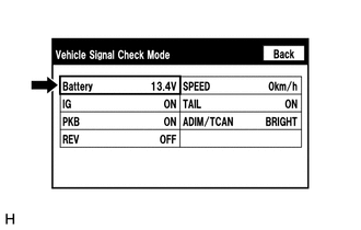
(b) Check that the battery voltage.
Standard voltage:
11 to 14 V
HINT:
This display is updated once per second. As a result, it is normal for the display to lag behind the actual switch operation.
| NG | .gif) |
GO TO STEP 3 |
|
.gif)
|
2. |
CHECK FOR DTC |
(a) Clear the DTCs (See page .gif) ).
).
(b) Check for DTCs (See page ).
OK:
No DTCs are output.
| OK | |
USE SIMULATION METHOD TO CHECK |
| NG | |
REPLACE RADIO AND DISPLAY RECEIVER ASSEMBLY |
|
3. |
CHECK HARNESS AND CONNECTOR (RADIO AND DISPLAY RECEIVER ASSEMBLY POWER SOURCE) |
|
(a) Disconnect the radio and display receiver assembly connector. |
|
(b) Measure the voltage according to the value(s) in the table below.
Standard Voltage:
|
Tester Connection |
Condition |
Specified Condition |
|---|---|---|
|
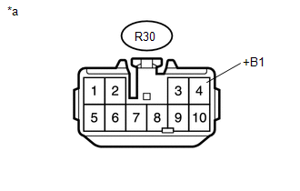
R30-4 (+B1) - Body ground |
Always |
11 to 14 V |
|
*a |
Front view of wire harness connector (to Radio and Display Receiver Assembly) |
| OK | |
REPLACE RADIO AND DISPLAY RECEIVER ASSEMBLY |
| NG | |
REPAIR OR REPLACE HARNESS OR CONNECTOR |
 USB Device Malfunction (B1585)
DESCRIPTION
This DTC is stored when a malfunction occurs in a connected device.
DTC No.
DTC Detection Condition
Trouble Area
B1585
USB De ...
 Short in GPS Antenna (B15C0,B15C1)
DESCRIPTION
These DTCs are stored when a malfunction occurs in the navigation antenna assembly.
DTC No.
DTC Detection Condition
Trouble Area
B15C0
...
Other materials:
Dtc Check / Clear
DTC CHECK / CLEAR
1. SUPPLEMENTAL RESTRAINT SYSTEM DTC CHECK (USING SST CHECK WIRE)
(a) Check the DTCs (Present DTCs).
(1) Turn the ignition switch to ON, and wait for approximately 60 seconds.
(2) Using SST, connect terminals TC and CG of the DLC3.
SST: 09843-18040
NOTICE:
Connect the term ...
Replacement
REPLACEMENT
PROCEDURE
1. RECOVER REFRIGERANT FROM REFRIGERATION SYSTEM
(a) Start up the engine.
(b) Turn the A/C switch to ON.
(c) Operate the cooler compressor with an engine speed of approximately 1,000
rpm for 5 to 6 minutes to circulate the refrigerant and collect the compressor oil
rem ...
Key information
The following keys are provided with the vehicle.
Vehicles without engine immobilizer
system
Master keys
Key number plate
Vehicles with engine immobilizer
system
Master keys
Key number plate
■Key number plate
Keep the plate in a safe place such as your wallet, not in the v ...
