Toyota Tacoma (2015-2018) Service Manual: Air Inlet Damper Control Servo Motor Circuit (B1442/42)
DESCRIPTION
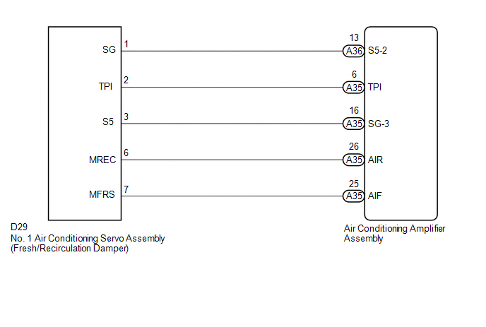
This No. 1 air conditioning servo assembly (fresh/recirculation damper) is controlled by the air conditioning amplifier assembly and moves the air inlet damper to the desired position.
|
DTC No. |
DTC Detection Condition |
Trouble Area |
|---|---|---|
|
B1442/42 |
Air inlet damper position sensor value does not change even if air conditioning amplifier assembly operates air inlet damper servo motor. |
|
WIRING DIAGRAM
PROCEDURE
|
1. |
READ VALUE USING TECHSTREAM |
(a) Connect the Techstream to the DLC3.
(b) Turn the ignition switch to ON.
(c) Turn the Techstream on.
(d) Operate the recirculation/fresh switch.
(e) Enter the following menus: Body Electrical / Air Conditioner / Data List.
(f) Check the value(s) by referring to the table below.
Air Conditioner|
Tester Display |
Measurement Item/Range |
Normal Condition |
Diagnostic Note |
|---|---|---|---|
|
Air Inlet Damper Position |
Air inlet damper servo motor actual position / Air inlet damper servo motor actual position / Min.: -14.0% Max.: 113.5% |
FRESH: 0.0% RECIRCULATION: 100.0% |
- |
|
Air Inlet Damper Target |
Air inlet damper servo motor target position / Min.: -14.0% Max.: 113.5% |
FRESH: 0.0% RECIRCULATION: 100.0% |
- |
OK:
The display is as specified in the Normal Condition column.
|
Result |
Proceed to |
|---|---|
|
NG |
A |
|
OK (When troubleshooting according to Problem Symptoms Table) |
B |
|
OK (When troubleshooting according to the DTC) |
C |
| B | .gif) |
PROCEED TO NEXT SUSPECTED AREA SHOWN IN PROBLEM SYMPTOMS TABLE |
| C | |
REPLACE AIR CONDITIONING AMPLIFIER ASSEMBLY |
|
.gif)
|
2. |
INSPECT NO. 1 AIR CONDITIONING SERVO ASSEMBLY (FRESH/RECIRCULATION DAMPER) |
(a) Remove the No. 1 air conditioning servo assembly (fresh/recirculation damper)
(See page .gif) ).
).
(b) Inspect the No. 1 air conditioning servo assembly (fresh/recirculation damper)
(See page ).
| NG | |
REPLACE NO. 1 AIR CONDITIONING SERVO ASSEMBLY (FRESH/RECIRCULATION DAMPER) |
|
|
3. |
CHECK HARNESS AND CONNECTOR (NO. 1 AIR CONDITIONING SERVO ASSEMBLY - AIR CONDITIONING AMPLIFIER ASSEMBLY) |
(a) Disconnect the D29 No. 1 air conditioning servo assembly (fresh/recirculation damper).
(b) Disconnect the A35 air conditioning amplifier assembly connector.
(c) Measure the resistance according to the value(s) in the table below.
Standard Resistance:
|
Tester Connection |
Condition |
Specified Condition |
|---|---|---|
|
D29-6 (MREC) - A35-26 (AIR) |
Always |
Below 1 Ω |
|
D29-7 (MFRS) - A35-25 (AIF) |
Always |
Below 1 Ω |
|
D29-6 (MREC) or A35-26 (AIR) - Body ground |
Always |
10 kΩ or higher |
|
D29-7 (MFRS) or A35-25 (AIF) - Body ground |
Always |
10 kΩ or higher |
| OK | |
REPLACE AIR CONDITIONING AMPLIFIER ASSEMBLY |
| NG | |
REPAIR OR REPLACE HARNESS OR CONNECTOR |
 Air Mix Damper Position Sensor Circuit (Driver Side) (B1436/36)
DESCRIPTION
This sensor detects the position of the air mix damper (for driver side) and
sends the appropriate signals to the air conditioning amplifier assembly. The position
sensor is built int ...
 Room Temperature Sensor Circuit (B1411/11)
DESCRIPTION
The cooler thermistor (room temperature sensor) is installed in the instrument
panel to detect the cabin temperature which is used to control the air conditioning
system AUTO mode. Th ...
Other materials:
Portable Player cannot be Registered
CAUTION / NOTICE / HINT
HINT:
Some versions of "Bluetooth" compatible audio players may not function, or the
function may be limited using the radio and display receiver assembly, even if the
portable audio player itself can play files (See page
).
PROCEDURE
1.
...
Air Fuel Ratio Sensor
Components
COMPONENTS
ILLUSTRATION
Removal
REMOVAL
PROCEDURE
1. REMOVE AIR FUEL RATIO SENSOR (for Bank 1 Sensor 1)
(a) Disconnect the air fuel ratio sensor connector.
(b) Disengage the clamp to separate the air fuel ratio sensor wire ...
Brake Signal Malfunction (B2284)
DESCRIPTION
This DTC is stored when the brake signal sent via direct line and the brake signal
sent via CAN communication do not match.
HINT:
When the cable is disconnected and reconnected to the negative (-) battery terminal,
the power source mode returns to the state it was in before the ca ...
