Toyota Tacoma (2015-2018) Service Manual: Wireless Door Lock Tuner Circuit Malfunction (B1242)
DESCRIPTION
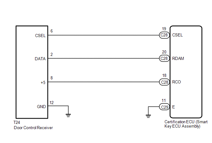
The door control receiver is used to receive radio waves relating to the entry functions of the electrical key transmitter sub-assembly. The certification ECU (smart key ECU assembly) decodes the requested electrical key transmitter sub-assembly by identifying a key code based on the radio waves received via the door control receiver. The door control receiver receives a signal from the electrical key transmitter sub-assembly and sends signals to the main body ECU (multiplex network body ECU) through the certification ECU (smart key ECU assembly). The certification ECU (smart key ECU assembly) then sends a command, according to the requested operation, to each ECU (ex. if door lock operation is requested, the certification ECU (smart key ECU assembly) sends a door lock command to the main body ECU (multiplex network body ECU)).
|
DTC No. |
DTC Detecting Condition |
Trouble Area |
|---|---|---|
|
B1242 |
|
|
WIRING DIAGRAM
CAUTION / NOTICE / HINT
NOTICE:
- When replacing or inspecting the door control receiver and wire harness, do not change the position or length of the wire harness. If the wire harness is too close to the door control receiver, smart and wireless function performance may be affected.
- Before performing the inspection, check that there are no problems related
to the CAN communication system (See page
.gif) ).
).
- When replacing the door control receiver, read the transmitter IDs (tire
pressure warning system) stored in the old ECU using the Techstream and
write them down before removal (See page
).*
- It is necessary to perform registration (See page
) of the transmitter IDs into the door
control receiver if the door control receiver has been replaced.*
- This DTC is not detected within 10 seconds after the engine switch turned
to off from on (IG).
- *: w/ Tire Pressure Warning System
PROCEDURE
|
1. |
CHECK CERTIFICATION ECU (SMART KEY ECU ASSEMBLY) |
|
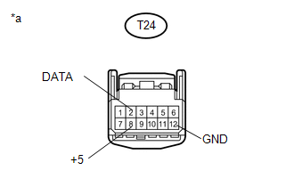
(a) Disconnect the door control receiver connector. |
|
(b) Measure the voltage and resistance according to the value(s) in the table below.
Standard Voltage:
|
Tester Connection |
Condition |
Specified Condition |
|---|---|---|
|
T24-8 (+5) - T24-12 (GND) |
Engine switch off, all doors closed and electrical key transmitter sub-assembly switch not pressed → electrical key transmitter sub-assembly switch pressed |
Below 1 V → 4.5 to 5.5 V (Pulse generation) |
|
T24-2 (DATA) - T24-12 (GND) |
Engine switch off |
11 to 14 V pulse generation at regular intervals |
Standard Resistance:
|
Tester Connection |
Condition |
Specified Condition |
|---|---|---|
|
T24-12 (GND) - Body ground |
Always |
Below 1 Ω |
|
*a |
Front view of wire harness connector (Door control receiver) |
| OK | .gif) |
REPLACE DOOR CONTROL RECEIVER |
|
.gif)
|
2. |
CHECK HARNESS AND CONNECTOR (DOOR CONTROL RECEIVER - CERTIFICATION ECU (SMART KEY ECU ASSEMBLY)) |
(a) Disconnect the certification ECU (smart key ECU assembly) connectors.
(b) Measure the resistance according to the value(s) in the table below.
Standard Resistance:
|
Tester Connection |
Condition |
Specified Condition |
|---|---|---|
|
C28-19 (CSEL) - T24-6 (CSEL) |
Always |
Below 1 Ω |
|
C28-20 (RDAM) - T24-2 (DATA) |
Always |
Below 1 Ω |
|
C28-18 (RCO) - T24-8 (+5) |
Always |
Below 1 Ω |
|
C29-11 (E) - Body ground |
Always |
Below 1 Ω |
|
T24-12 (GND) - Body ground |
Always |
Below 1 Ω |
|
C28-19 (CSEL) or T24-6 (CSEL) - Body ground |
Always |
10 kΩ or higher |
|
C28-22 (RDAM) or T24-2 (DATA) - Body ground |
Always |
10 kΩ or higher |
|
C28-18 (RCO) or T24-8 (+5) - Body ground |
Always |
10 kΩ or higher |
| OK | |
REPLACE CERTIFICATION ECU (SMART KEY ECU ASSEMBLY) |
| NG | |
REPAIR OR REPLACE HARNESS OR CONNECTOR |
 Diagnostic Trouble Code Chart
DIAGNOSTIC TROUBLE CODE CHART
HINT:
If a trouble code is output during the DTC check, inspect the trouble areas listed
for that code. For details of the code, refer to "See page" in the ...

Other materials:
Fuel Tank Cap
Inspection
INSPECTION
PROCEDURE
1. INSPECT FUEL TANK CAP ASSEMBLY
(a) Check the appearance of the fuel tank cap assembly.
(1) Check that there is no deformation or damage to the fuel tank cap assembly
or fuel tank cap gasket.
*1
Fuel Tank Cap Gasket
If the ...
System Description
SYSTEM DESCRIPTION
1. CRUISE CONTROL SYSTEM
The cruise control system makes it possible to drive at a desired speed without
using the accelerator pedal. ECM controls the throttle opening angle based on signals
from switches and sensors.
The microcomputer which controls the cruise control syst ...
Installing child restraints
Follow the child restraint system manufacturer’s instructions. Firmly secure
child restraints to the seats using the LATCH anchors or a seat belt. Attach the
top tether strap when installing a child restraint.
The lap/shoulder belt can be used if your child restraint system is not compatible ...
