
Toyota Tacoma (2005–2015) Owners Manual: Windshield wipers and washer
■ Without intermittent type
 Type A
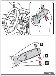
 Low speed windshield wiper
operation
Low speed windshield wiper
operation
 High speed windshield wiper operation
 Temporary operation
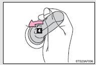
 Washer operation
 Type B
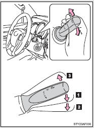
 Low speed windshield wiper operation
 High speed windshield wiper operation
 Temporary operation
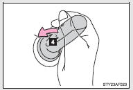
 Washer operation
■ Intermittent wiper with interval adjuster
Wiper intervals can be adjusted for intermittent operation (when
 or
or
 is selected).
 Type A
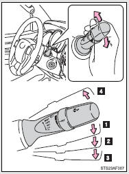
 Intermittent windshield wiper operation
 Low speed windshield wiper operation
 High speed windshield wiper operation
 Temporary operation
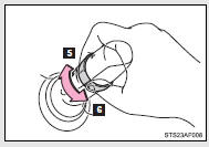
 Increases the intermittent windshield
wiper frequency
Increases the intermittent windshield
wiper frequency
 Decreases the intermittent windshield
wiper frequency
Decreases the intermittent windshield
wiper frequency
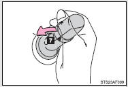
 Washer/wiper dual operation
Wipers will automatically operate a couple of times after the washer squirts.
 Type B
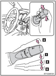
 Intermittent windshield wiper
operation
Intermittent windshield wiper
operation
 Low speed windshield wiper operation
 High speed windshield wiper operation
 Temporary operation
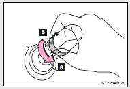
 Increases the intermittent windshield
wiper frequency
Increases the intermittent windshield
wiper frequency
 Decreases the intermittent windshield
wiper frequency
Decreases the intermittent windshield
wiper frequency
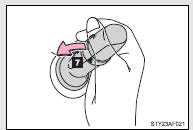
 Washer/wiper dual operation
Wipers will automatically operate a couple of times after the washer squirts.
■The windshield wiper and washer can be operated when
The engine switch must be in the ON position.
■If no windshield washer fluid sprays
Check that the washer nozzles are not blocked and if there is washer fluid in the windshield washer fluid reservoir.
NOTICE
■When the windshield is dry
Do not use the wipers, as they may damage the windshield.
■When there is no washer fluid spray from the nozzle
Damage to the washer fluid pump may be caused if the lever is pulled toward you and held continually.
■When a nozzle becomes blocked
Do not try to clear it with a pin or other object. The nozzle will be damaged.
 Fog light switch
The fog lights improve visibility in difficult driving conditions, such as
in rain or fog.
■The fog lights can be turned on only when
The headlights are on low beam. ...

Other materials:
On-vehicle Inspection
ON-VEHICLE INSPECTION
PROCEDURE
1. INSPECT SIDE AIRBAG SENSOR ASSEMBLY (for Vehicle not Involved in Collision)
(a) Perform a diagnostic system check (See page
).
2. INSPECT SIDE AIRBAG SENSOR ASSEMBLY (for Vehicle Involved in Collision and
Airbag has not Deployed)
(a) Perform a diagnostic s ...
Door Control Receiver
Components
COMPONENTS
ILLUSTRATION
Removal
REMOVAL
PROCEDURE
1. REMOVE ROOF HEADLINING ASSEMBLY (for Double Cab)
(See page )
2. REMOVE ROOF HEADLINING ASSEMBLY (for Access Cab)
(See page )
3. REMOVE DOOR CONTROL RECEIVER (w/o Tire Pressure Warning System)
(a) Disconne ...
Installation
INSTALLATION
PROCEDURE
1. INSTALL TRANSMISSION FLOOR SHIFT ASSEMBLY
(a) Install the transmission floor shift assembly to the vehicle body with the
4 bolts.
Torque:
14 N·m {143 kgf·cm, 10 ft·lbf}
(b) Attach the 4 clamps to connect the wire harness to the transmission floor
shift assembl ...
