Toyota Tacoma (2015-2018) Service Manual: Washer Nozzle
Components
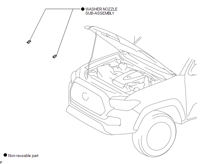
COMPONENTS
ILLUSTRATION
On-vehicle Inspection
ON-VEHICLE INSPECTION
PROCEDURE
1. INSPECT WASHER NOZZLE SUB-ASSEMBLY
(a) Operate the washer nozzle sub-assembly and check the position that the washer fluid hits the windshield.
Standard:
Washer fluid hits the windshield glass in the areas shown in the illustration.
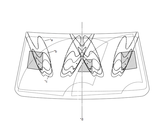 Text in Illustration
|
*a |
Upper Limit |
*b |
Standard |
|
*c |
Lower Limit |
*d |
Vehicle center line |
.png) |
Reference |
- |
- |
HINT:
If the result is not as specified, replace the washer nozzle sub-assembly.
Adjustment
ADJUSTMENT
PROCEDURE
1. REMOVE WASHER NOZZLE SUB-ASSEMBLY
.gif)
2. ADJUST WASHER NOZZLE SUB-ASSEMBLY
(a) Select a washer nozzle so that the contact area is within the standard. Replace the washer nozzle with the selected one.
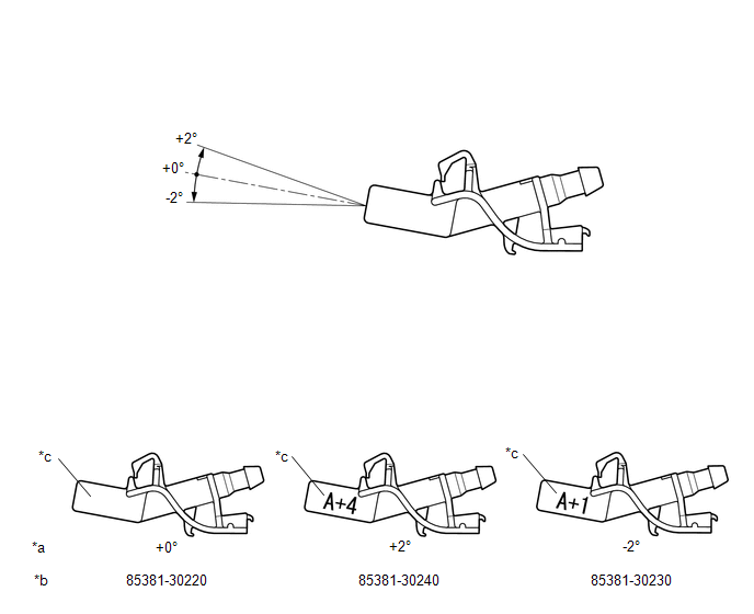 Text in Illustration
|
*a |
Washer Fluid Spray Angle |
*b |
Part Number |
|
*c |
Identification Mark |
- |
- |
3. INSTALL WASHER NOZZLE SUB-ASSEMBLY
Installation
INSTALLATION
PROCEDURE
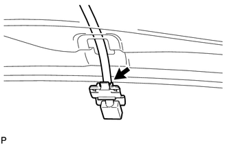
1. INSTALL WASHER NOZZLE SUB-ASSEMBLY
(a) Connect a new washer nozzle sub-assembly to the washer hose.
|
(b) Engage the 2 claws to install the washer nozzle sub-assembly as shown in the illustration. |
|
2. INSPECT WASHER NOZZLE SUB-ASSEMBLY
.gif)
3. ADJUST WASHER NOZZLE SUB-ASSEMBLY
Removal
REMOVAL
PROCEDURE
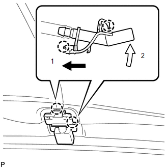
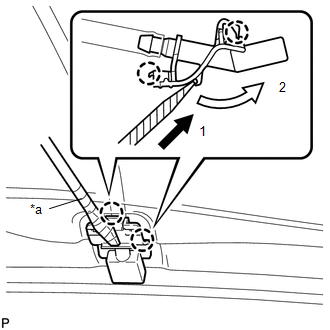
1. REMOVE WASHER NOZZLE SUB-ASSEMBLY
HINT:
Use the same procedure for both sides.
|
(a) Using a screwdriver with its tip wrapped in protective tape, disengage the 2 claws to separate the washer nozzle sub-assembly as shown in the illustration. Text in Illustration
NOTICE: Do not damage the windshield glass. |
|
|
(b) Remove the washer nozzle sub-assembly from the washer hose. NOTICE: Washer nozzle sub-assembly cannot be reused. |
|
 Washer Motor
Components
COMPONENTS
ILLUSTRATION
On-vehicle Inspection
ON-VEHICLE INSPECTION
PROCEDURE
1. INSPECT WINDSHIELD WASHER MOTOR AND PUMP ASSEMBLY
HINT:
This check should be performed with th ...

Other materials:
While Alarm is Armed, Battery is Reconnected but Alarm does not Sound
DESCRIPTION
While the alarm is armed, the EEPROM inside the main body ECU (multiplex network
body ECU) will remember the armed state even if the battery is disconnected, and
the alarm will sound when the battery is reconnected.
If the alarm does not sound when the battery is reconnected, the a ...
Front Differential Oil Temperature Sensor Circuit High (P17C8)
DESCRIPTION
This DTC is output when a short to B+ or open circuit in the oil temperature
sensor is detected.
DTC No.
Detection Item
DTC Detection Condition
Trouble Area
P17C8
Front Differential Oil Temperature Sensor Circuit ...
Installation
INSTALLATION
PROCEDURE
1. INSTALL FRONT BUMPER ASSEMBLY
(a) w/ Fog Light:
(1) Connect the 2 connectors.
(b) Engage the 3 claws and guide to install the front bumper assembly.
(c) Remove the protective tape.
(d) Install the 6 clips.
(e) Engage the clamp.
(f) Connect the connector.
(g) Insta ...
