Toyota Tacoma (2015-2018) Service Manual: Back-up Light Switch
Components
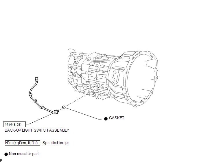
COMPONENTS
ILLUSTRATION
Inspection
INSPECTION
PROCEDURE
1. INSPECT BACK-UP LIGHT SWITCH ASSEMBLY
|
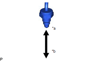
(a) Measure the resistance according to the value(s) in the table below. Text in Illustration
Standard Resistance:
If the result is not as specified, replace the back-up light switch assembly. |
|
Removal
REMOVAL
PROCEDURE
1. REMOVE SHIFT LEVER BOOT ASSEMBLY
.gif)
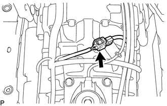
2. REMOVE BACK-UP LIGHT SWITCH ASSEMBLY
|
(a) Disconnect the connector. |
|
|
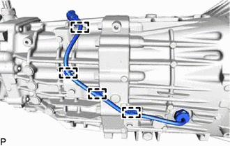
(b) Detach the 4 clamps. |
|
|
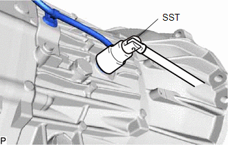
(c) Using SST, remove the back-up light switch assembly and gasket from the transmission case. SST: 09817-16011 |
|
Installation
INSTALLATION
PROCEDURE
1. INSTALL BACK-UP LIGHT SWITCH ASSEMBLY
|
(a) Using SST, install a new gasket and the back-up light switch assembly to the transmission case. SST: 09817-16011 Torque: 44 N·m {449 kgf·cm, 32 ft·lbf} |
|
.png)
(b) Attach the 4 clamps.
(c) Connect the connector.
2. INSTALL SHIFT LEVER BOOT ASSEMBLY
.gif)

 Counter Gear
...
Other materials:
Microphone Amplifier
Components
COMPONENTS
ILLUSTRATION
*A
w/o Sliding Roof
*B
w/ Sliding Roof
*1
TELEPHONE MICROPHONE ASSEMBLY
-
-
Removal
REMOVAL
PROCEDURE
1. REMOVE ROOF HEADLINING ASSEMBLY (for Double ...
Fuel information
Your vehicle must use only unleaded gasoline.
Select octane rating 87 (Research Octane Number 91) or higher. Use of unleaded
gasoline with an octane rating lower than 87 may result in engine knocking. Persistent
knocking can lead to engine damage.
At minimum, the gasoline you use should meet t ...
Installation
INSTALLATION
CAUTION / NOTICE / HINT
HINT:
Perform "Inspection After Repairs" after replacing the fuel delivery pipe assembly
LH (fuel pressure sensor) (See page ).
PROCEDURE
1. INSTALL FUEL PIPE PLUG SUB-ASSEMBLY
(a) Install a new O-ring, new No. 1 fuel injector back-up ring, new ...
