Toyota Tacoma (2015-2018) Service Manual: Turn Signal Switch Circuit
DESCRIPTION
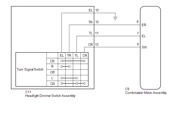
The combination meter assembly receives the turn signal switch information and controls the turn signal lights.
WIRING DIAGRAM
PROCEDURE
|
1. |
READ VALUE USING TECHSTREAM (TURN SIGNAL SWITCH) |
(a) Connect the Techstream to the DLC3.
(b) Turn the ignition switch to ON.
(c) Turn the Techstream on.
(d) Enter the following menus: Body Electrical / Combination Meter / Data List.
(e) According to the display on the Techstream, read the Data List.
Combination Meter|
Tester Display |
Measurement Item/Range |
Normal Condition |
Diagnostic Note |
|---|---|---|---|
|
Turn Signal Switch (Right) |
Turn signal switch (right) signal / ON or OFF |
ON: Turn signal switch (right) on OFF: Turn signal switch (right) off |
- |
|
Turn Signal Switch (Left) |
Turn signal switch (left) signal / ON or OFF |
ON: Turn signal switch (left) on OFF: Turn signal switch (left) off |
- |
|
Turn Switch Signal (Full Turn) |
Turn signal switch (full turn) signal / ON or OFF |
ON: Turn signal switch (left or right) on OFF: Turn signal switch (left and right) off |
- |
OK:
Normal conditions listed above are displayed.
| OK | .gif) |
PROCEED TO NEXT SUSPECTED AREA SHOWN IN PROBLEM SYMPTOMS TABLE |
|
.gif)
|
2. |
INSPECT HEADLIGHT DIMMER SWITCH ASSEMBLY |
|
(a) Remove the C11 headlight dimmer switch assembly. |
|
(b) Measure the resistance according to the value(s) in the table below.
Standard Resistance:
|
Tester Connection |
Condition |
Specified Condition |
|---|---|---|
|
12 (TR) - 15 (EL) |
Turn signal switch in neutral position |
10 kΩ or higher |
|
11 (TL) - 15 (EL) |
Turn signal switch in neutral position |
10 kΩ or higher |
|
13 (CR) - 15 (EL) |
Turn signal switch in neutral position |
10 kΩ or higher |
|
12 (TR) - 15 (EL) |
Turn signal switch in right turn position |
Below 1 Ω |
|
13 (CR) - 15 (EL) |
Turn signal switch in full right turn position |
Below 1 Ω |
|
11 (TL) - 15 (EL) |
Turn signal switch in left turn position |
Below 1 Ω |
|
13 (CR) - 15 (EL) |
Turn signal switch in full left turn position |
Below 1 Ω |
|
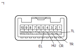
*1 |
Component without harness connected (Headlight Dimmer Switch Assembly) |
| NG | |
REPLACE HEADLIGHT DIMMER SWITCH ASSEMBLY |
|
|
3. |
CHECK HARNESS AND CONNECTOR (HEADLIGHT DIMMER SWITCH ASSEMBLY - COMBINATION METERASSEMBLY AND BODY GROUND) |
(a) Disconnect the C9 combination meter assembly connector.
(b) Disconnect the C11 headlight dimmer switch assembly connector.
(c) Measure the resistance according to the value(s) in the table below.
Standard Resistance:
|
Tester Connection |
Condition |
Specified Condition |
|---|---|---|
|
C11-12 (TR) - C9-8 (ER) |
Always |
Below 1 Ω |
|
C11-11 (TL) - C9-7 (EL) |
Always |
Below 1 Ω |
|
C11-13 (CR) - C9-9 (SW) |
Always |
Below 1 Ω |
|
C11-12 (TR) - Body ground |
Always |
10 kΩ or higher |
|
C11-11 (TL) - Body ground |
Always |
10 kΩ or higher |
|
C11-13 (CR) - Body ground |
Always |
10 kΩ or higher |
|
C11-15 (EL) - Body ground |
Always |
Below 1 Ω |
| OK | |
PROCEED TO NEXT SUSPECTED AREA SHOWN IN PROBLEM SYMPTOMS TABLE |
| NG | |
REPAIR OR REPLACE HARNESS OR CONNECTOR |
 IG Signal Circuit
DESCRIPTION
This circuit detects whether the ignition switch is ON or off, and sends this
information to the main body ECU (multiplex network body ECU).
WIRING DIAGRAM
CAUTION / NOTICE / HINT
...
 ACC Signal Circuit
DESCRIPTION
This circuit detects whether the ignition switch is ACC or off, and sends this
information to the main body ECU (multiplex network body ECU).
WIRING DIAGRAM
CAUTION / NOTICE / HINT
...
Other materials:
Connecting Bluetooth®
The following can be performed using Bluetooth® wireless communication: ■
A portable audio player can be operated and listened to via multimedia system
■ Hands-free phone calls can be made via a cellular phone
In order to use wireless communication, register and connect a Bluetooth ...
Removal
REMOVAL
PROCEDURE
1. REMOVE MANUAL TRANSMISSION ASSEMBLY
(See page )
2. REMOVE CLUTCH RELEASE FORK SUB-ASSEMBLY
(a) Remove the clutch release fork sub-assembly with the clutch release
bearing assembly from the manual transmission assembly.
...
Problem Symptoms Table
PROBLEM SYMPTOMS TABLE
HINT:
Use the table below to help determine the cause of problem symptoms.
If multiple suspected areas are listed, the potential causes of the symptoms
are listed in order of probability in the "Suspected Area" column of the
table. Check each sy ...
