Toyota Tacoma (2015-2018) Service Manual: Transponder Key Amplifier
Components
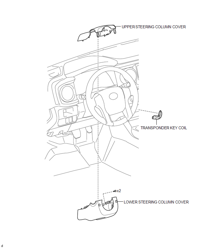
COMPONENTS
ILLUSTRATION
Installation
INSTALLATION
PROCEDURE
1. INSTALL TRANSPONDER KEY COIL
|
(a) Engage the 2 claws to install the transponder key coil. |
|
(b) Connect the connector.
2. INSTALL UPPER STEERING COLUMN COVER
(See page .gif) )
)
3. INSTALL LOWER STEERING COLUMN COVER
(See page
)
Removal
REMOVAL
PROCEDURE
1. REMOVE LOWER STEERING COLUMN COVER
(See page .gif) )
)
2. REMOVE UPPER STEERING COLUMN COVER
(See page
)
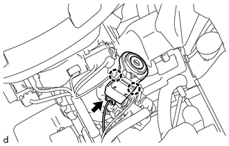
3. REMOVE TRANSPONDER KEY COIL
|
(a) Disconnect the connector. |
|
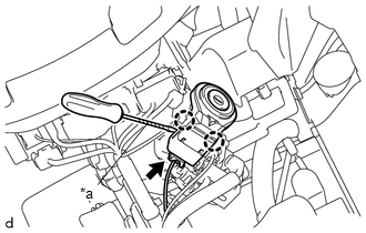
(b) Using a screwdriver with its tip wrapped in protective tape, disengage the 2 claws to remove the transponder key coil.
Text in Illustration|
*a |
Protective Tape |
 Security Indicator Light Does not Blink
DESCRIPTION
The transponder key ECU assembly blinks the security indicator light
when the immobiliser is set (no key is in the ignition key cylinder).
w/ Theft Deterrent System:
...
 Transponder Key Ecu
Components
COMPONENTS
ILLUSTRATION
Installation
INSTALLATION
PROCEDURE
1. INSTALL TRANSPONDER KEY ECU
(a) Engage the 2 guides to move the transponder key ECU in the direction
...
Other materials:
Terminals Of Ecu
TERMINALS OF ECU
1. CHECK AIR CONDITIONING AMPLIFIER ASSEMBLY
(a) Disconnect the A36 air conditioning amplifier assembly connector.
(b) Measure the voltage and resistance according to the value(s) in the table
below.
HINT:
Measure the values on the wire harness side with the connector disco ...
Low Power Supply Voltage Malfunction (C1241)
DESCRIPTION
If a malfunction is detected in the power supply circuit, the skid control ECU
(brake actuator assembly) stores this DTC and the fail-safe function prohibits ABS
operation.
This DTC is stored when the +BS terminal voltage deviates from the DTC detection
condition due to a malfunc ...
Open in Rear Floor Electrical Key Oscillator Circuit (B27A6)
DESCRIPTION
The certification ECU (smart key ECU assembly) generates a request signal and
transmits the signal to the No. 2 indoor electrical key antenna assembly (rear floor).
For the No. 2 indoor electrical key antenna assembly (rear floor) to detect when
the electrical key transmitter sub- ...
