Toyota Tacoma (2015-2018) Service Manual: Terminals Of Ecu
TERMINALS OF ECU
1. CHECK CERTIFICATION ECU (SMART KEY ECU ASSEMBLY)
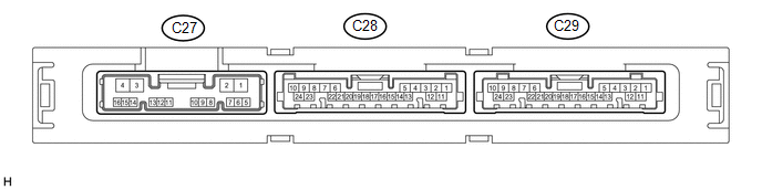
(a) Disconnect the C27 and C29 certification ECU (smart key ECU assembly) connectors.
(b) Measure the voltage and resistance according to the value(s) in the table below.
HINT:
Measure the values on the wire harness side with the connector disconnected.
|
Tester Connection |
Input/ Output |
Wiring Color |
Terminal Description |
Condition |
Specified Condition |
Related Data List Item |
|---|---|---|---|---|---|---|
|
C27-12 (STA) - C29-11 (E) |
Input |
Y - W-B |
When starting the engine, this monitors the voltage sent from terminal STAR to the starter relay to judge whether the engine is "being started". |
20°C (68°F) |
106.78 to 115.98 Ω |
- |
|
C27-10 (STAR) - Body ground |
Input/ Output |
V - Body ground |
Outputs voltage to the starter relay
HINT: When Hi is selected, a start request signal (STAR) will not be output even though a start request signal (STSW) is input. |
Shift lever in any position other than P or N → Shift lever in P or N (at 20°C (68°F)) |
10 kΩ or higher → 107.05 to 116.33 Ω |
- |
|
Receives neutral start switch (P, N position detection) signal
|
Perform the following operations except while the engine is cranking:
|
30 kΩ or higher → 107.05 to 116.33 Ω |
Neutral SW/ Clutch SW |
|||
|
C27-14 (NE) - Body ground |
Input |
BE - Body ground |
Engine speed signal |
Always |
10 kΩ or higher |
Engine Conditio n |
|
C27-2 (STP1) - Body ground |
Input |
L - Body ground |
Stop light switch signal |
Brake pedal depressed → Brake pedal released |
9 V or higher → 1 V or less |
Stop Light Switch1 |
|
C29-10 (+B) - C29-11 (E) |
Input |
P - W-B |
Power source |
Always |
11 to 14 V |
- |
|
C29-23 (SLP) - C29-11 (E) |
Input |
BE - W-B |
Steering lock position signal |
Steering locked |
10 kΩ or higher |
Steering Unlock Switch |
|
C29-22 (P) - C29-11 (E) |
Input |
V - W-B |
P position signal |
Shift lever in P → Shift lever not in P |
30 kΩ or higher → Below 200 Ω |
Shift P Signal |
|
C29-11 (E) - Body ground |
- |
W-B - Body ground |
GND |
Always |
Below 1 Ω |
- |
|
C29-18 (SSW2) - Body ground |
Input |
GR - Body ground |
SSW2 contact signal HINT: Backup for SSW1. Behaves the same way as SSW1. |
Engine switch pushed → Engine switch not pushed |
Below 15 Ω → 10 kΩ or higher |
Start Switch2 |
|
C29-16 (SSW1) - Body ground |
Input |
BE - Body ground |
SSW1 contact signal |
Engine switch pushed → Engine switch not pushed |
Below 15 Ω → 10 kΩ or higher |
Start Switch1 |
|
C29-9 (ACCD) - Body ground |
Output |
R - Body ground |
ACC signal |
20°C (68°F) |
130.92 to 190.74 Ω |
ACC Relay Monitor |
|
C27-3 (IG1D) - Body ground |
Output |
B - Body ground |
IG signal |
20°C (68°F) |
87.32 to 127.14 Ω |
IG Relay Monitor (Outside ) |
|
C27-4 (CUTB) - C29-11 (E) |
Input |
GR - W-B |
Dark current cut pin*1 |
Always |
11 to 14 V |
- |
|
C29-5 (SPD) - Body ground |
Input |
V - Body ground |
Vehicle speed signal |
Always |
30 kΩ or higher |
Vehicle Speed Signal |
- *1: In order to prevent the vehicle battery from being depleted when the vehicle is shipped long distances, a fuse that cuts unnecessary electrical load while the vehicle is being shipped is set in the circuit. If the fuse is removed, the circuit becomes open. If the fuse that is between the vehicle battery and terminal CUTB is removed and the circuit is open, the certification ECU (smart key ECU assembly) changes to a certain control mode (example: the transmission of electric waves every 0.25 seconds that form the detection area stops).
(c) Reconnect the C27 and C29 certification ECU (smart key ECU assembly) connectors.
(d) Measure the voltage and check for pulses according to the value(s) in the table below.
|
Tester Connection |
Input/ Output |
Wiring Color |
Terminal Description |
Condition |
Specified Condition |
Related Data List Item |
|---|---|---|---|---|---|---|
|
C27-12 (STA) - C29-11 (E) |
Input |
Y - W-B |
When starting the engine, this monitors the voltage sent from terminal STAR to the starter relay to judge whether the engine is "being started". |
With the brake pedal depressed, the engine switch is pressed and held (starter on) → After approximately 1 second has elapsed, the engine switch is released (starter off) |
6 V or higher*1 → 1.0 V or less |
- |
|
C27-10 (STAR) - C29-11 (E) |
Input/ Output |
V - W-B |
Outputs voltage to the starter relay
HINT: When Hi is selected, a start request signal (STAR) will not be output even though a start request signal (STSW) is input. |
With the brake pedal depressed, the engine switch is pressed and held → After approximately 1 second has elapsed, the engine switch is released |
6 V or higher*1 → 1.0 V or less |
- |
|
Receives neutral start switch (P, N position detection) signal
|
Perform the following operations except while the engine is cranking:
|
9 V or higher → 2.7 V or less |
Neutral SW/ Clutch SW |
|||
|
C27-14 (NE) - C29-11 (E) |
Input |
BE - W-B |
Engine speed signal |
Idling (engine warmed up) |
Pulse generation (See waveform 1) |
Engine Conditio n |
|
C27-2 (STP1) - C29-11 (E) |
Input |
L - W-B |
Stop light switch signal |
Brake pedal depressed → Brake pedal released |
1 V or less → 9 V or higher |
Stop Light Switch1 |
|
C29-23 (SLP) - C29-11 (E) |
Input |
BE - W-B |
Steering lock position signal |
Steering locked → Steering unlocked |
11 to 14 V → 1.5 V or less |
Steering Unlock Switch |
|
C29-24 (SLR+) - C29-11 (E) |
Output |
Y - W-B |
Steering lock motor operation command signal (Steering lock motor operation permission signal sent from the certification ECU (smart key ECU assembly)) |
When a door is opened, the steering lock motor will be operated if all of the following conditions are met:
|
Pulse generation (See waveform 2) |
- |
|
C29-22 (P) - C29-11 (E) |
Input |
V - W-B |
P position signal |
Shift lever in P → Shift lever not in P |
9 V or higher → 2.76 V or less |
Shift P Signal |
|
C29-18 (SSW2) - C29-11 (E) |
Input |
GR - W-B |
SSW2 contact signal HINT: Backup for SSW1. Behaves the same way as SSW1. |
Engine switch not pushed → Engine switch pushed |
9 V or higher → 1 V or less |
Start Switch2 |
|
C29-16 (SSW1) - C29-11 (E) |
Input |
BE - W-B |
SSW1 contact signal |
Engine switch not pushed → Engine switch pushed |
9 V or higher → 1 V or less |
Start Switch1 |
|
C29-9 (ACCD) - C29-11 (E) |
Output |
R - W-B |
ACC signal |
Engine switch off → Engine switch on (ACC) |
1 V or less → 8.5 V or higher |
ACC Relay Monitor |
|
C27-3 (IG1D) - C29-11 (E) |
Output |
B - W-B |
IG signal |
Engine switch on (ACC) → Engine switch on (IG) |
1 V or less → 9 V or higher |
IG Relay Monitor (Outside ) |
|
C29-5 (SPD) - C29-11 (E) |
Input |
V - W-B |
Vehicle speed signal |
Vehicle being driven at approximately 5 km/h (3 mph) |
Pulse generation (See waveform 3) |
ACC Relay Monitor |
- *1: While the engine is cranking, the battery voltage may drop to approximately 6 V.
HINT:
- The waveform of the steering lock actuator motor stopped can be checked without performing any particular operation.
- The waveform of the steering lock actuator motor operating can be checked
if either of the following operations is performed:
- To unlock the steering, bring the electrical key transmitter sub-assembly into the cabin and turn the engine switch on (ACC) or on (IG).
- To lock the steering, open a door with the engine switch off and the shift lever in P.
(e) Using an oscilloscope, check the waveform of the ECU.
NOTICE:
The oscilloscope waveform shown in the illustration is an example for reference only. Noise, chattering, etc. are not shown.
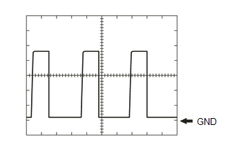
(1) Waveform 1
|
Item |
Content |
|---|---|
|
Tester Connection |
C27-14 (NE) - C29-11 (E) |
|
Tool Setting |
2 V/DIV., 2 ms./DIV. |
|
Condition |
Idling (engine warmed up) |
HINT:
The wavelength becomes shorter as the engine speed increases.
(2) Waveform 2

|
Item |
Content |
|---|---|
|
Tester Connection |
C29-24 (SLR+) - C29-11 (E) |
|
Tool Setting |
2 V/DIV., 200 ms./DIV. |
|
Condition |
Steering lock motor stopped → Steering lock motor operating → Steering lock motor stopped |
|
*a |
Steering lock motor not operating |
|
*b |
Steering lock motor operating |
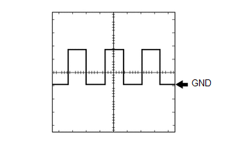
(3) Waveform 3
|
Item |
Content |
|---|---|
|
Tester Connection |
C29-5 (SPD) - C29-11 (E) |
|
Tool Setting |
5 V/DIV., 200 ms./DIV. |
|
Condition |
Vehicle being driven at approx. 5 km/h (3 mph) |
HINT:
The wavelength becomes shorter as the engine speed increases.
2. CHECK STEERING LOCK ECU (STEERING LOCK ACTUATOR OR UPR BRACKET ASSEMBLY)
See page .gif)
3. CHECK ENGINE SWITCH
See page
 Dtc Check / Clear
DTC CHECK / CLEAR
NOTICE:
When using the Techstream with the engine switch off, connect the Techstream
to the DLC3 and turn a courtesy light switch on and off at intervals of 1.5 seconds
or less ...
 Data List / Active Test
DATA LIST / ACTIVE TEST
1. DATA LIST
HINT:
Using the Techstream to read the Data List allows the values or states of switches,
sensors, actuators and other items to be read without removing any p ...
Other materials:
Brake Warning Light does not Come ON
DESCRIPTION
Refer to Brake Warning Light Remains ON (See page
).
WIRING DIAGRAM
Refer to Brake Warning Light Remains ON (See page
).
CAUTION / NOTICE / HINT
NOTICE:
When replacing the skid control ECU (master cylinder solenoid), perform
calibration (See page
).
Inspect ...
Data List / Active Test
DATA LIST / ACTIVE TEST
1. DATA LIST
HINT:
Using the Techstream to read the Data List allows the values or states of switches,
sensors, actuators and other items to be read without removing any parts. This non-intrusive
inspection can be very useful because intermittent conditions or signals ...
Installation
INSTALLATION
PROCEDURE
1. INSTALL FRONT BUMPER ASSEMBLY
(a) w/ Fog Light:
(1) Connect the 2 connectors.
(b) Engage the 3 claws and guide to install the front bumper assembly.
(c) Remove the protective tape.
(d) Install the 6 clips.
(e) Engage the clamp.
(f) Connect the connector.
(g) Insta ...
