Toyota Tacoma (2015-2018) Service Manual: Terminals Of Ecu
TERMINALS OF ECU
1. CHECK COMBINATION METER ASSEMBLY
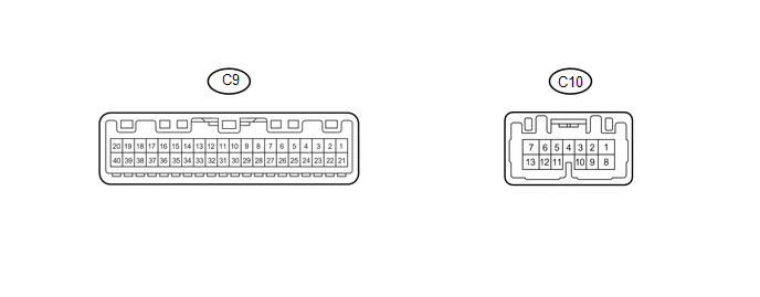
(a) Measure the resistance and voltage according to the value(s) in the table below.
|
Terminal No. (Symbol) |
Wiring Color |
Terminal Description |
Condition |
Specified Condition |
|---|---|---|---|---|
|
C9-19 (B) - Body ground |
P - Body ground |
Battery power supply |
Always |
11 to 14 V |
|
C9-20 (IG+) - Body ground |
BE - Body ground |
Ignition switch power supply |
Ignition switch ON |
11 to 14 V |
|
Ignition switch off |
Below 1 V |
|||
|
C9-17 (EP) - Body ground |
W-B - Body ground |
Ground |
Always |
Below 1 Ω |
|
C9-18 (ES) - Body ground |
W-B - Body ground |
Ground |
Always |
Below 1 Ω |
|
C9-1 (CANH) - Body ground |
G - Body ground |
CAN communication line |
Always |
200 Ω or higher |
|
C9-2 (CANL) - Body ground |
W - Body ground |
CAN communication line |
Always |
200 Ω or higher |
- If the result is not as specified, the combination meter assembly may have a malfunction.
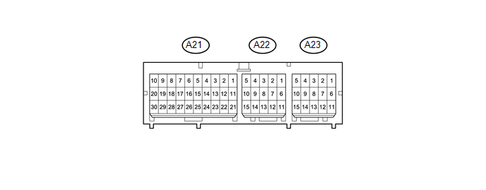
2. CHECK CENTER AIRBAG SENSOR ASSEMBLY
|
Terminal No. |
Terminal Symbol |
Destination |
|---|---|---|
|
A23-12 |
FSR+ |
Occupant classification ECU |
|
A23-13 |
FSR- |
Occupant classification ECU |
|
A22-11 |
LBE+ |
Front seat inner belt assembly (for driver side) |
|
A22-12 |
LBE- |
Front seat inner belt assembly (for driver side) |
3. CHECK OCCUPANT CLASSIFICATION ECU

(a) Measure the voltage and check for pulses according to the value(s) in the table below.
|
Terminal No. (Symbol) |
Wiring Color |
Terminal Description |
Condition |
Specified Condition |
|---|---|---|---|---|
|
O5-1 (+B) - O5-3 (GND) |
R - W-B |
Battery power supply |
Always |
11 to 14 V |
|
O5-2 (DIA) - O5-3 (GND) |
W - W-B |
Diagnosis (DLC3) |
Ignition switch ON |
Pulse generation |
|
O5-3 (GND) - Body ground |
W-B - Body ground |
Ground |
Always |
Below 1 V |
|
O5-7 (IG) - O5-3 (GND) |
BE - W-B |
Ignition switch power supply |
Ignition switch ON |
11 to 14 V |
|
O5-8 (FSR+) - O5-4 (FSR-) |
W - B |
Center airbag sensor assembly communication line |
Ignition switch ON |
Pulse generation |
|
O5-9 (BSW) - O5-5 (BGND) |
G - P-G |
Front passenger side buckle switch line |
Always |
4 to 14 V |
|
O4-1 (SGD1) - O5-3 (GND) |
L - W-B |
Front occupant classification sensor LH ground line |
Always |
Below 1 V |
|
O4-2 (SGD2) - O5-3 (GND) |
BE - W-B |
Front occupant classification sensor RH ground line |
Always |
Below 1 V |
|
O4-3 (SGD3) - O5-3 (GND) |
P-G - W-B |
Rear occupant classification sensor LH ground line |
Always |
Below 1 V |
|
O4-4 (SGD4) - O5-3 (GND) |
B-R - W-B |
Rear occupant classification sensor RH ground line |
Always |
Below 1 V |
|
O4-11 (SVC1) - O4-1 (SGD1) |
B-L - L |
Front occupant classification sensor LH power supply line |
Ignition switch ON, a load applied to front occupant classification sensor LH |
4.9 to 5.1 V |
|
O4-12 (SVC2) - O4-2 (SGD2) |
LG-B - BE |
Front occupant classification sensor RH power supply line |
Ignition switch ON, a load applied to front occupant classification sensor RH |
4.9 to 5.1 V |
|
O4-5 (SVC3) - O4-3 (SGD3) |
B - P-G |
Rear occupant classification sensor LH power supply line |
Ignition switch ON, a load applied to rear occupant classification sensor LH |
4.9 to 5.1 V |
|
O4-6 (SVC4) - O4-4 (SGD4) |
GR-L - B-R |
Rear occupant classification sensor RH power supply line |
Ignition switch ON, a load applied to rear occupant classification sensor RH |
4.9 to 5.1 V |
|
O4-7 (SIG1) - O4-1 (SGD1) |
G - L |
Front occupant classification sensor LH signal line |
Ignition switch ON, a load applied to front occupant classification sensor LH |
0 to 5.1 V |
|
O4-8 (SIG2) - O4-2 (SGD2) |
R-L - BE |
Front occupant classification sensor RH signal line |
Ignition switch ON, a load applied to front occupant classification sensor RH |
0 to 5.1 V |
|
O4-9 (SIG3) - O4-3 (SGD3) |
R-B - P-G |
Rear occupant classification sensor LH signal line |
Ignition switch ON, a load applied to rear occupant classification sensor LH |
0 to 5.1 V |
|
O4-10 (SIG4) - O4-4 (SGD4) |
L-R - B-R |
Rear occupant classification sensor RH signal line |
Ignition switch ON, a load applied to rear occupant classification sensor RH |
0 to 5.1 V |
- If the result is not as specified, the occupant classification ECU may have a malfunction.
 Problem Symptoms Table
PROBLEM SYMPTOMS TABLE
HINT:
Use the table below to help determine the cause of problem symptoms.
If multiple suspected areas are listed, the potential causes of the symptoms
are lis ...
 Driver Side Seat Belt Warning Light does not Operate
DESCRIPTION
When the ignition switch is ON, the airbag sensor assembly transmits front seat
inner belt status signals to the combination meter assembly through CAN. If the
driver seat belt is not ...
Other materials:
Clutch Release Cylinder(for Rc62f)
Components
COMPONENTS
ILLUSTRATION
Disassembly
DISASSEMBLY
PROCEDURE
1. REMOVE CLUTCH RELEASE CYLINDER KIT
(a) Remove the boot from the cylinder body.
(b) Remove the push rod from the boot.
(c) Using compressed air, remove the piston together with the spring
from the cy ...
AUTO LSD Indicator Light does not Come ON
DESCRIPTION
The AUTO LSD does not operate even if the VSC OFF switch is pressed under the
following conditions:
The brake system is faulty.
The temperature inside the hydraulic brake booster increases and the
AUTO LSD operation is suspended.
The rear differential is locked.
...
Components
COMPONENTS
ILLUSTRATION
HINT:
The following specifications are for BD20D (w/o Differential Lock). BD20D differentials
are equipped with M8 rear differential carrier to rear axel housing fasteners.
ILLUSTRATION
ILLUSTRATION
...
