Toyota Tacoma (2015-2018) Service Manual: Terminals Of Ecu
TERMINALS OF ECU
1. CHECK DRIVER SIDE JUNCTION BLOCK AND MAIN BODY ECU (MULTIPLEX NETWORK BODY ECU)
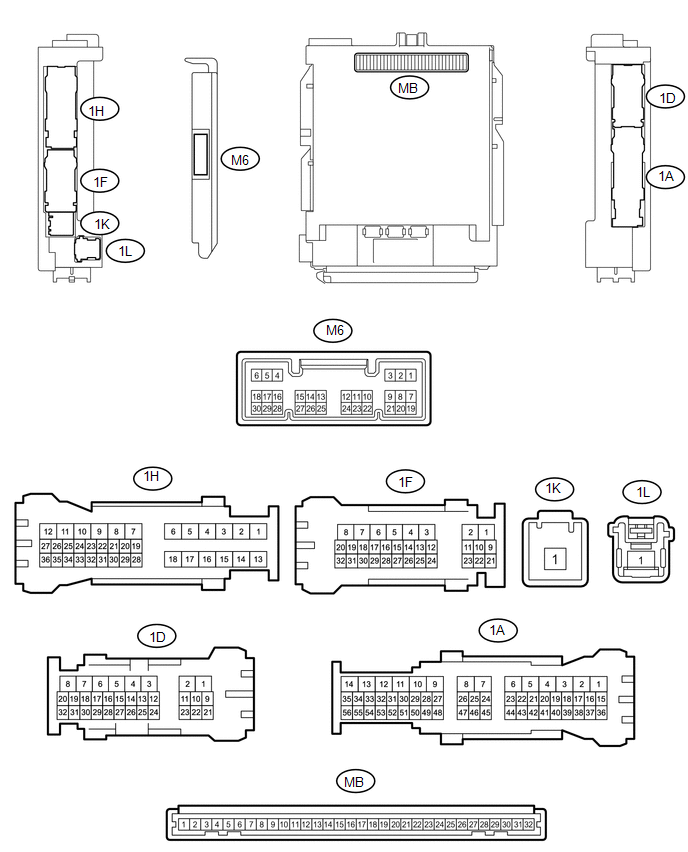
(a) Disconnect the MB main body ECU (multiplex network body ECU) connectors.
(b) Measure the voltage and resistance according to the value(s) in the table below.
HINT:
Measure the values on the wire harness side with the connectors disconnected.
|
Tester Connection |
Wiring Color |
Terminal Description |
Condition |
Specified Condition |
|---|---|---|---|---|
|
MB-11(GND1) - Body ground |
- |
Ground |
Always |
Below 1 Ω |
|
MB-31 (BECU) - Body ground |
- |
Battery power supply |
Always |
11 to 14 V |
|
MB-30 (ACC) - Body ground |
- |
ACC power supply |
Engine switch ACC |
11 to 14 V |
|
MB-30 (ACC) - Body ground |
- |
ACC power supply |
Engine switch off |
Below 1 V |
|
MB-32 (IG) - Body ground |
- |
IG power supply |
Engine switch ON |
11 to 14 V |
|
MB-32 (IG) - Body ground |
- |
IG power supply |
Engine switch off |
Below 1 V |
If the result is not as specified, there may be a malfunction in the wire harness.
(c) Reconnect the MB main body ECU (multiplex network body ECU) connectors.
(d) Measure the voltage and check for pulses according to the value(s) in the table below.
|
Tester Connection |
Wiring Color |
Terminal Description |
Condition |
Specified Condition |
|---|---|---|---|---|
|
1D-1 (ACT+) - Body ground |
R - Body ground |
Door lock motor unlock drive output (except driver door) |
Door control switch (power window regulator master switch assembly) or driver door key cylinder off |
Below 1 V |
|
Door control switch (power window regulator master switch assembly) or driver door key cylinder unlocked |
11 to 14 V |
|||
|
1H-12 (ACT+) - Body ground |
LA-R - Body ground |
Door lock motor unlock drive output (except driver door) |
Door control switch (power window regulator master switch assembly) or driver door key cylinder off |
Below 1 V |
|
Door control switch (power window regulator master switch assembly) or driver door key cylinder unlocked |
11 to 14 V |
|||
|
1H-10 (ACT-) - Body ground |
LA-G - Body ground |
Door lock motor lock drive output (all doors) |
Door control switch (power window regulator master switch assembly) or driver door key cylinder off |
Below 1 V |
|
Door control switch (power window regulator master switch assembly) or driver door key cylinder locked |
11 to 14 V |
|||
|
1D-3 (ACT-) - Body ground |
G - Body ground |
Door lock motor lock drive output (all doors) |
Door control switch (power window regulator master switch assembly) or driver door key cylinder off |
Below 1 V |
|
Door control switch (power window regulator master switch assembly) or driver door key cylinder locked |
11 to 14 V |
|||
|
1D-2 (ACTD) - Body ground |
B - Body ground |
Driver door lock motor unlock drive output |
Door control switch (power window regulator master switch assembly) or driver door key cylinder off |
Below 1 V |
|
Door control switch (power window regulator master switch assembly) or driver door key cylinder unlocked |
11 to 14 V |
|||
|
M6-27 (FRCY) - Body ground |
LG - Body ground |
Front door courtesy light switch RH input |
Front door RH open |
Below 1 V |
|
M6-27 (FRCY) - Body ground |
LG - Body ground |
Front door courtesy light switch RH input |
Front door RH open |
11 to 14 V |
|
M6-6 (FLCY) - Body ground |
Y - Body ground |
Front door courtesy light switch LH input |
Front door LH open |
Below 1 V |
|
M6-6 (FLCY) - Body ground |
Y - Body ground |
Front door courtesy light switch LH input |
Front door LH closed |
11 to 14 V |
|
1H-36 (LCTY) - Body ground |
P - Body ground |
Rear door courtesy light switch LH input*1 Upper access panel lock assembly LH input*2 Lower access panel lock assembly LH input*2 |
Rear door LH open |
Below 1 V |
|
1H-36 (LCTY) - Body ground |
P - Body ground |
Rear door courtesy light switch LH input*1 Upper access panel lock assembly LH input*2 Lower access panel lock assembly LH input*2 |
Rear door LH closed |
Pulse generation |
|
1D-30 (RCTY) - Body ground |
V - Body ground |
Rear door courtesy light switch RH input*1 Upper access panel lock assembly RH input*2 Lower access panel lock assembly RH input*2 |
Rear door RH open |
Below 1 V |
|
1D-30 (RCTY) - Body ground |
V - Body ground |
Rear door courtesy light switch RH input*1 Upper access panel lock assembly RH input*2 Lower access panel lock assembly RH input*2 |
Rear door RH closed |
Pulse generation |
|
1D-11 (LSFL) - Body ground |
P - Body ground |
Front door LH unlock detection switch input |
Front door LH unlocked |
Below 1 V |
|
1D-11 (LSFL) - Body ground |
P - Body ground |
Front door LH unlock detection switch input |
Engine switch off, all doors closed and front door LH locked |
Pulse generation |
|
1D-24 (LSFR) - Body ground |
GR - Body ground |
Front door RH unlock detection switch input |
Front door RH unlocked |
Below 1 V |
|
1D-24 (LSFR) - Body ground |
GR - Body ground |
Front door RH unlock detection switch input |
Engine switch off, all doors closed and front door RH locked |
Pulse generation |
|
1A-41 (LSR) - Body ground |
Y - Body ground |
Rear door RH unlock detection switch input |
Rear door RH or LH unlocked |
Below 1 V |
|
1A-41 (LSR) - Body ground |
Y - Body ground |
Rear door RH unlock detection switch input |
Engine switch off, all doors closed and rear door RH and LH locked |
Pulse generation |
|
1H-27 (LSR) - Body ground |
L - Body ground |
Rear door LH unlock detection switch input |
Rear door LH or RH unlocked |
Below 1 V |
|
1H-27 (LSR) - Body ground |
L - Body ground |
Rear door LH unlock detection switch input |
Engine switch off, all doors closed and rear door LH and RH locked |
Pulse generation |
|
1F-29 (BZR) - Body ground |
Y - Body ground |
Wireless door lock buzzer signal |
Wireless door lock buzzer off |
Below 1 V |
|
1F-29 (BZR) - Body ground |
Y - Body ground |
Wireless door lock buzzer signal |
Wireless door lock buzzer on |
Pulse generation |
- *1: for Double Cab
- *2: for Access Cab
If the result is not as specified, there may be a malfunction in the wire harness.
2. CHECK CERTIFICATION ECU (SMART KEY ECU ASSEMBLY)
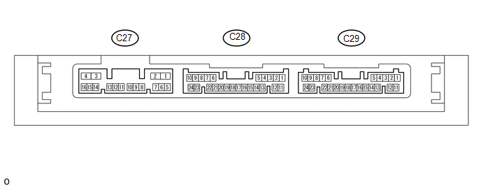
(a) Disconnect the C27 and C29 certification ECU (smart key ECU assembly) connector.
(b) Measure the resistance and voltage according to the value(s) in the table below.
HINT:
Measure the values on the wire harness side with the connector disconnected.
|
Tester Connection |
Wiring Color |
Terminal Description |
Condition |
Specified Condition |
|---|---|---|---|---|
|
C29-11 (E) - Body ground |
W-B - Body ground |
Ground |
Always |
Below 1 Ω |
|
C29-10 (+B) - Body ground |
P - Body ground |
Battery power supply |
Always |
11 to 14 V |
|
C27-4 (CUTB) - Body ground |
GR - Body ground |
Dark current cut fuse pin input signal |
Always |
11 to 14 V |
If the result is not as specified, there may be a malfunction in the wire harness.
(c) Reconnect the C27 and C29 certification ECU (smart key ECU assembly) connector.
(d) Measure the voltage according to the value(s) in the table below.
|
Tester Connection |
Wiring Color |
Terminal Description |
Condition |
Specified Condition |
|---|---|---|---|---|
|
C27-3 (IG1D) - C29-11 (E) |
B - W-B |
IG power supply |
Engine switch on (IG) |
11 to 14 V |
|
Engine switch off |
Below 1 V |
|||
|
C28-19 (CSEL) - C29-11 (E) |
SB - W-B |
Communication channel switching circuit |
Engine switch off, all doors closed and electrical key transmitter sub-assembly switch not pressed → electrical key transmitter sub-assembly switch pressed → electrical key transmitter sub-assembly switch released |
Below 1 V → 4.5 to 6.0 V → Below 1 V |
|
C28-20 (RDAM) - C29-11 (E) |
G - W-B |
RF Signal input circuit |
Engine switch off |
11 to 14 V pulse generation at regular intervals |
|
C28-18 (RCO) - C29-11 (E) |
L - W-B |
Wireless tuner power supply output circuit |
Engine switch off, all doors closed and electrical key transmitter sub-assembly switch not pressed → electrical key transmitter sub-assembly switch pressed |
Below 1 V → 4.5 to 5.5 V |
If the result is not as specified, the certification ECU (smart key ECU assembly) may have a malfunction.
3. CHECK DOOR CONTROL RECEIVER

(a) Disconnect the T24 door control receiver connector.
(b) Measure the resistance and voltage according to the value(s) in the table below.
HINT:
Measure the values on the wire harness side with the connector disconnected.
|
Tester Connection |
Wiring Color |
Terminal Description |
Condition |
Specified Condition |
|---|---|---|---|---|
|
T24-7 (+B) - Body ground |
BE - Body ground |
Battery (power supply) |
Always |
10 to 16 V |
|
T24-12 (GND) - Body ground |
W-B - Body ground |
Ground |
Always |
Below 1 Ω |
If the result is not as specified, there may be a malfunction in the wire harness.
(c) Reconnect the T24 door control receiver connector.
(d) Measure the voltage according to the value(s) in the table below.
|
Tester Connection |
Wiring Color |
Terminal Description |
Condition |
Specified Condition |
|---|---|---|---|---|
|
T24-6 (CSEL) - T24-12 (GND) |
SB - W-B |
Smart system receiving channel switching signal input |
Engine switch off, all doors closed and electrical key transmitter sub-assembly switch not pressed → electrical key transmitter sub-assembly switch pressed → electrical key transmitter sub-assembly switch released |
Below 1 V → 4.5 to 6.0 V → Below 1 V |
|
T24-2 (DATA) - T24-12 (GND) |
G - W-B |
Smart system recovery code output |
Engine switch off, all doors closed and electrical key transmitter sub-assembly switch not pressed → electrical key transmitter sub-assembly switch pressed → electrical key transmitter sub-assembly switch released |
Below 1 V → 10 to 16 V → Below 1 V |
|
T24-8 (+5) - T24-12 (GND) |
L - W-B |
Receive mode switching signal input |
Engine switch off, all doors closed and electrical key transmitter sub-assembly switch not pressed → electrical key transmitter sub-assembly switch pressed |
Below 1 V → 4.5 to 5.5 V |
If the result is not as specified, the certification ECU (smart key ECU assembly) may have a malfunction.
 Dtc Check / Clear
DTC CHECK / CLEAR
1. CHECK FOR DTC
HINT:
When using the Techstream with the engine switch off to troubleshoot:
Connect the Techstream to the DLC3 and turn a courtesy light switch on and off
at 1 ...
 Data List / Active Test
DATA LIST / ACTIVE TEST
1. DATA LIST
HINT:
Using the Techstream to read the Data List allows the values or states of switches,
sensors, actuators and other items to be read without removing any p ...
Other materials:
Radio Receiver Power Source Circuit
DESCRIPTION
This is the power source circuit to operate the radio and display receiver assembly.
WIRING DIAGRAM
CAUTION / NOTICE / HINT
NOTICE:
Inspect the fuses for circuits related to this system before performing
the following inspection procedure.
PROCEDURE
...
Fail-safe Chart
FAIL-SAFE CHART
1. FAIL-SAFE OPERATION AND DEACTIVATION CONDITION
DIFFERENTIAL SYSTEM (w/ Differential Lock)
DTC No.
Fail-safe Operation
Fail-safe Deactivation Condition
U0122
All switching prohibited
When rear differential is locked ...
Removal
REMOVAL
PROCEDURE
1. REMOVE PROPELLER SHAFT WITH CENTER BEARING ASSEMBLY
(a) Place matchmarks on the propeller shaft flange yoke and differential
flange.
Text in Illustration
*a
Matchmark
...
