Toyota Tacoma (2015-2018) Service Manual: Terminals Of Ecu
TERMINALS OF ECU
1. TERMINAL INSPECTION
 Text in Illustration
|
*a |
Component without harness connected (Steering Lock ECU (Steering Lock Actuator or UPR Bracket Assembly)) |
- |
- |
(a) Measure the voltage and resistance according to the value(s) in the table below.
|
Terminal No. (Symbol) |
Input/Output |
Wiring Color |
Terminal Description |
Condition |
Specified Condition |
Related Data List Item |
|---|---|---|---|---|---|---|
|
S45-1 (GND) - Body ground |
- |
W-B - Body ground |
Ground* |
Always |
Below 1 ╬® |
- |
|
S45-3 (IGE) - S45-1 (GND) |
Input |
Y - W-B |
Steering lock motor activation command signal (motor activation command signal sent from certification ECU (smart key ECU assembly)) |
Any door opened when conditions below met, and then steering lock motor activated:
|
Pulse generation (see waveform) |
Smart Key
|
|
S45-4 (SLP1) - S45-1 (GND) |
Output |
BE - W-B |
Steering lock bar position signal (output signal from steering unlock sensor) |
Steering locked ŌåÆ unlocked |
11 to 14 V ŌåÆ Below 1.5 V |
Smart Key
|
|
S45-5 (LIN) - S45-1 (GND) |
Input/Output |
L - W-B |
LIN communication line |
- |
- |
Smart Key
|
|
S45-6 (IG2) - S45-1 (GND) |
Input |
B - W-B |
Power source mode signal (IG2 power supply input for entire steering lock actuator assembly)* |
Engine switch off ŌåÆ engine switch on (IG) |
Below 1 V ŌåÆ 11 to 14 V |
- |
|
S45-7 (B) - Body ground |
Input |
R - Body ground |
Power source* |
Always |
11 to 14 V |
- |
- *: When there is a problem with the power source input, the certification ECU (smart key ECU assembly) may store DTC B2786.
NOTICE:
There is 1 motor and 2 sensors built into the steering lock actuator assembly.
HINT:
- When taking measurements when the lock motor is stopped, it is not necessary to perform any operations.
- In order to take measurements when the lock motor is operating, perform
either of the following operations:
- To unlock the steering, carry the key and turn the engine switch on (ACC) or on (IG).
- To lock the steering, turn the engine switch off with the shift lever in P, and then open a door.
(1) Waveform
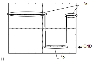
|
Item |
Content |
|---|---|
|
Tester Connection |
S45-3 (IGE) - S45-1 (GND) |
|
Tool Setting |
2 V/DIV., 200 ms./DIV. |
|
Vehicle Condition |
Steering lock motor not operating ŌåÆ Operating ŌåÆ Not operating |
|
*a |
Steering Lock Motor not Operating |
|
*b |
Steering Lock Motor Operating |
 Dtc Check / Clear
DTC CHECK / CLEAR
NOTICE:
The steering lock ECU (steering lock actuator or UPR bracket assembly)
does not store history DTCs. If any DTCs are output, confirm and record
them as soon ...
 Data List / Active Test
DATA LIST / ACTIVE TEST
1. READ DATA LIST
HINT:
Using the Techstream to read the Data List allows the values or states of switches,
sensors, actuators and other items to be read without removing ...
Other materials:
Diagnostic Trouble Code Chart
DIAGNOSTIC TROUBLE CODE CHART
Power Window Control System
DTC Code
Detection Item
See page
B2311
Power Window Motor Malfunction
B2312
Power Window Switch Malfunction
...
Confirm Cellular Phone Functionality
PROCEDURE
1.
CHECK THE CUSTOMER'S CELLULAR PHONE COMPATIBILITY
(a) Go to TIS "Bluetooth" Compatibility Portal and check if the cellular phone
is compatible.
Result
Result
Proceed to
Cellular phone is compatibl ...
Towing Tail Relay
Inspection
INSPECTION
PROCEDURE
1. INSPECT TOWING TAIL RELAY
(a) Check the resistance.
(1) Using an ohmmeter, measure the resistance between the terminals.
Standard:
Tester Connection
Specified Condition
3-5
10 k╬® or higher
...
