Toyota Tacoma (2015-2018) Service Manual: Terminals Of Ecu
TERMINALS OF ECU
1. CHECK 4 WHEEL DRIVE CONTROL ECU
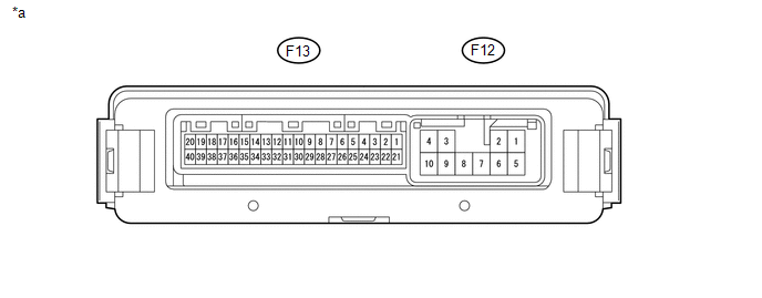 Text in Illustration
|
*a |
Component with harness connected (4 Wheel Drive Control ECU) |
- |
- |
(a) Measure the resistance and voltage according to the value(s) in the table below.
|
Terminal No. (Symbol) |
Wiring Color |
Terminal Description |
Condition |
Specified Condition |
|---|---|---|---|---|
|
F13-1 (4WD) - F12-10 (GND) |
BE - W-B*3 LG - W-B*4 |
4WD detection switch signal input |
Ignition switch ON Transfer position 2WD |
10 to 14 V |
|
Ignition switch ON Transfer position 4WD |
Below 1.5 V |
|||
|
F13-2 (ADD) - F12-10 (GND) |
G - W-B |
A.D.D. position switch input |
Ignition switch ON Transfer position 2WD (A.D.D. actuator Free) |
10 to 14 V |
|
Ignition switch ON Transfer position 4WD (A.D.D. actuator Lock) |
Below 1.5 V |
|||
|
F13-3 (4WDL) - F12-10 (GND) |
Y - W-B |
L4 detection switch signal input |
Ignition switch ON Transfer position not in L4 |
10 to 14 V |
|
Ignition switch ON Transfer position L4 |
Below 1.5 V |
|||
|
F13-5 (DT) - F13-25 (DGND) |
BE - V |
Oil temperature sensor signal input |
Ignition switch ON |
0.9 to 4.9 V |
|
F13-7 (DL2) - F12-10 (GND) |
P - W-B |
A.D.D. actuator limit switch input |
Ignition switch ON Transfer position 2WD (A.D.D. actuator Free) |
10 to 14 V |
|
Ignition switch ON Transfer position 4WD (A.D.D. actuator Lock) |
Below 1.5 V |
|||
|
F13-8 (DL1) - F12-10 (GND) |
LG - W-B |
A.D.D. actuator limit switch input |
Ignition switch ON Transfer position 2WD (A.D.D. actuator Free) |
Below 1.5 V |
|
Ignition switch ON Transfer position 4WD (A.D.D. actuator Lock) |
10 to 14 V |
|||
|
F13-9 (TL3) - F12-10 (GND) |
B - W-B |
Transfer shift actuator limit switch input |
Ignition switch ON TL3 terminal limit switch off (transfer 2WD or L4) |
10 to 14 V |
|
Ignition switch ON TL3 terminal limit switch on (transfer H4) |
Below 1.5 V |
|||
|
F13-10 (TL2) - F12-10 (GND) |
SB - W-B |
Transfer shift actuator limit switch input |
Ignition switch ON TL2 terminal limit switch off (transfer 2WD or H4) |
10 to 14 V |
|
Ignition switch ON TL2 terminal limit switch on (transfer L4) |
Below 1.5 V |
|||
|
F13-11 (TL1) - F12-10 (GND) |
Y - W-B |
Transfer shift actuator limit switch input |
Ignition switch ON TL1 terminal limit switch off (transfer H4 or L4) |
10 to 14 V |
|
Ignition switch ON TL1 terminal limit switch on (transfer 2WD) |
Below 1.5 V |
|||
|
F13-13 (LO) - F12-10 (GND) |
V - W-B |
Transfer position switch input |
Ignition switch ON Transfer position switch 2WD |
10 to 14 V |
|
Ignition switch ON Transfer position switch H4 |
Below 1.5 V |
|||
|
Ignition switch ON Transfer position switch L4 |
Below 1.5 V |
|||
|
F13-14 (2-4) - F12-10 (GND) |
GR - W-B |
Transfer position switch input |
Ignition switch ON Transfer position switch 2WD |
Below 1.5 V |
|
Ignition switch ON Transfer position switch H4 |
Below 1.5 V |
|||
|
Ignition switch ON Transfer position switch L4 |
10 to 14 V |
|||
|
F13-18 (MTN) - F12-10 (GND)*2 |
V - W-B |
Clutch start switch input |
Ignition switch ON Clutch pedal released |
10 to 14 V |
|
Ignition switch ON Clutch pedal depressed |
Below 2 V |
|||
|
F13-20 (CANH) - F13-40 (CANL) |
BE - W |
HIGH-level CAN bus wire - LOW-level CAN bus wire |
Ignition switch off Cable disconnected from negative (-) battery terminal |
54 to 69 Ω |
|
F13-21 (+B) - F12-10 (GND) |
W - W-B |
ECU power supply |
Always |
11 to 14 V |
|
F12-2 (DM1) - F12-10 (GND) |
R - W-B |
A. D. D. shift motor output |
Ignition switch ON Transfer position switch H4 to 2WD (during A.D.D. actuator Lock to Free operation) |
Pulse generation (see waveform 1) |
|
F12-4 (IG) - F12-10 (GND) |
Y - W-B |
ECU and actuator power supply |
Ignition switch ON |
11 to 14 V |
|
F12-6 (DM2) - F12-10 (GND) |
SB - W-B |
A. D. D. shift motor output |
Ignition switch ON Transfer position switch 2WD to H4 (during A.D.D. actuator Free to Lock operation) |
Pulse generation (see waveform 1) |
|
F12-7 (TM2) - F12-10 (GND) |
L - W-B |
Transfer shift motor output |
Ignition switch ON Shift lever in N*1 Shift lever in neutral*2 Transfer position switch turned from 2WD to H4 (switching from 2WD to H4) Transfer position switch turned from H4 to L4 (switching from H4 to L4) |
Pulse generation (see waveform 2) |
|
F12-8 (TM1) - F12-10 (GND) |
G - W-B |
Transfer shift motor output |
Ignition switch ON Shift lever in N*1 Shift lever in neutral*2 Transfer position switch turned from L4 to H4 (switching from L4 to H4) |
Pulse generation |
|
F12-10 (GND) - Body ground |
W-B - Body ground |
Ground |
Always |
Below 1 Ω |
- *1: for Automatic Transmission
- *2: for Manual Transmission
- *3: 2GR-FKS
- *4: 2TR-FE
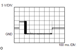
(b) Waveform 1
(1) When a gear is engaged and switching is performed
|
Item |
Content |
|---|---|
|
Tester Connection |
F12-2 (DM1) - F12-10 (GND) |
|
Tool Setting |
5 V/DIV., 100 ms./DIV. |
|
Condition |
Ignition switch ON Transfer position switch H4 to 2WD (during A.D.D. actuator Lock to Free operation) |
|
Item |
Content |
|---|---|
|
Tester Connection |
F12-6 (DM2) - F12-10 (GND) |
|
Tool Setting |
5 V/DIV., 100 ms./DIV. |
|
Condition |
Ignition switch ON Transfer position switch 2WD to H4 (during A.D.D. actuator Free to Lock operation) |
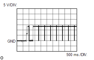
(2) When a gear is not engaged and switching is not performed
|
Item |
Content |
|---|---|
|
Tester Connection |
F12-2 (DM1) - F12-10 (GND) |
|
Tool Setting |
5 V/DIV., 500 ms./DIV. |
|
Condition |
Ignition switch ON Transfer position switch H4 to 2WD (during A.D.D. actuator Lock to Free operation) |
|
Item |
Content |
|---|---|
|
Tester Connection |
F12-6 (DM2) - F12-10 (GND) |
|
Tool Setting |
5 V/DIV., 500 ms./DIV. |
|
Condition |
Ignition switch ON Transfer position switch 2WD to H4 (during A.D.D. actuator Free to Lock operation) |
(c) Waveform 2
(1) When a gear is engaged and switching is performed
|
Item |
Content |
|---|---|
|
Tester Connection |
F12-8 (TM1) - F12-10 (GND) |
|
Tool Setting |
5 V/DIV., 100 ms./DIV. |
|
Condition |
Ignition switch ON Shift lever in N*1 Shift lever in neutral*2 Transfer position switch turned from L4 to H4 (switching from L4 to H4) |
- *1: for Automatic Transmission
- *2: for Manual Transmission
|
Item |
Content |
|---|---|
|
Tester Connection |
F12-7 (TM2) - F12-10 (GND) |
|
Tool Setting |
5 V/DIV., 100 ms./DIV. |
|
Condition |
Ignition switch ON Shift lever in N*1 Shift lever in neutral*2 Transfer position switch turned from 2WD to H4 (switching from 2WD to H4) Transfer position switch turned from H4 to L4 (switching from H4 to L4) |
- *1: for Automatic Transmission
- *2: for Manual Transmission
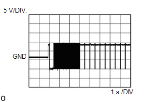
(2) When a gear is not engaged and switching is not performed
|
Item |
Content |
|---|---|
|
Tester Connection |
F12-8 (TM1) - F12-10 (GND) |
|
Tool Setting |
5 V/DIV., 1 s./DIV. |
|
Condition |
Ignition switch ON Shift lever in N*1 Shift lever in neutral*2 Transfer position switch turned from L4 to H4 (switching from L4 to H4) |
- *1: for Automatic Transmission
- *2: for Manual Transmission
|
Item |
Content |
|---|---|
|
Tester Connection |
F12-7 (TM2) - F12-10 (GND) |
|
Tool Setting |
5 V/DIV., 1 s./DIV. |
|
Condition |
Ignition switch ON Shift lever in N*1 Shift lever in neutral*2 Transfer position switch turned from 2WD to H4 (switching from 2WD to H4) Transfer position switch turned from H4 to L4 (switching from H4 to L4) |
- *1: for Automatic Transmission
- *2: for Manual Transmission
 Problem Symptoms Table
PROBLEM SYMPTOMS TABLE
HINT:
Use the table below to help determine the cause of problem symptoms.
If multiple suspected areas are listed, the potential causes of the symptoms
are lis ...
 Data List / Active Test
DATA LIST / ACTIVE TEST
NOTICE:
In the table below, the values listed under "Normal Condition" are reference
values. Do not depend solely on these reference values when deciding whether ...
Other materials:
TC and CG Terminal Circuit
DESCRIPTION
Tire pressure warning system DTCs can be checked by connecting terminals 13 (TC)
and 4 (CG) of the DLC3. The DTCs are indicated by blinking the tire pressure warning
light.
WIRING DIAGRAM
PROCEDURE
1.
CHECK CAN COMMUNICATION SYSTEM
(a) Check for ...
On-vehicle Inspection
ON-VEHICLE INSPECTION
PROCEDURE
1. INSPECT OCCUPANT DETECTION ECU (for Vehicle not Involved in Collision)
(a) Perform a diagnostic system check (See page
).
2. INSPECT OCCUPANT DETECTION ECU (for Vehicle Involved in Collision)
(a) Perform a diagnostic system check (See page
).
(b) Even if ...
Speaker Circuit
DESCRIPTION
If there is a short in a speaker circuit, the radio and display receiver
assembly detects it and stops output to the speakers.
Thus sound cannot be heard from the speakers even if there is no malfunction
in the radio and display receiver assembly or speakers.
If a ...
