Toyota Tacoma (2015-2018) Service Manual: Terminals Of Ecu
TERMINALS OF ECU
FORWARD RECOGNITION CAMERA
NOTICE:
- DTCs may be output when connectors are disconnected during inspection. Therefore, be sure to clear the DTCs using the Techstream once the inspection has been completed.
- Do not apply excessive force to the forward recognition camera connector.
(a) Check forward recognition camera

|
Terminal No. (Symbol) |
Wiring Color |
Terminal Description |
Condition |
Specified Condition |
|---|---|---|---|---|
|
F46-7 (IGB) - Body ground |
BE - Body ground |
Power source |
Ignition switch ON |
11 to 14 V |
|
Ignition switch off |
Below 1 V |
|||
|
F46-10 (GND) - Body ground |
W-B - Body ground |
Ground |
Always |
Below 1 Ω |
|
F46-5 (CA1P) - Body ground |
L - Body ground |
CAN communication signal |
Ignition switch ON |
Pulse generation (Waveform 1) |
|
F46-11 (CA1N) - Body ground |
W - Body ground |
Pulse generation (Waveform 2) |
||
|
F46-6 (CANH) - Body ground |
B - Body ground |
Pulse generation (Waveform 1) |
||
|
F46-12 (CANL) - Body ground |
W - Body ground |
Pulse generation (Waveform 2) |
(b) WAVEFORM 1
(1) CAN communication signal
|
Item |
Content |
|---|---|
|
Terminal Name |
Between F46-5 (CA1P) and F46-10 (GND) Between F46-6 (CANH) and F46-10 (GND) |
|
Tester Range |
1 V/DIV., 10 ÎĽsec./DIV. |
|
Condition |
Ignition switch ON |
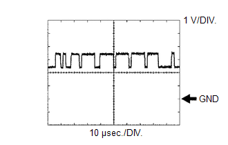
HINT:
The waveform varies depending on the CAN communication signal.
(c) WAVEFORM 2
(1) CAN communication signal
|
Item |
Content |
|---|---|
|
Terminal Name |
Between F46-11 (CA1N) and F46-10 (GND) Between F46-12 (CANL) and F46-10 (GND) |
|
Tester Range |
1 V/DIV., 10 ÎĽsec./DIV. |
|
Condition |
Ignition switch ON |
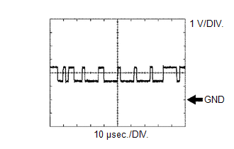
HINT:
The waveform varies depending on the CAN communication signal.
 Diagnosis System
DIAGNOSIS SYSTEM
CHECK DLC3
(a) Check the DLC3.
Click here
FUNCTION OF WARNING INDICATOR AND MESSAGE
(a) If the lane departure alert system is not functioning properly, the driver
is warned b ...
 Dtc Check / Clear
DTC CHECK / CLEAR
CHECK DTC
(a) Connect the Techstream to the DLC3.
(b) Turn the ignition switch to ON.
(c) Turn the Techstream on.
(d) Enter the following menus: Chassis / LKA/LDA / Trouble Code ...
Other materials:
Initialization
INITIALIZATION
1. RESET MEMORY
NOTICE:
Perform Reset Memory (AT initialization) when replacing the automatic
transmission assembly, transmission valve body assembly or any of the shift
solenoid valves.
Reset Memory can be performed only with the Techstream.
HINT:
The E ...
IG2 Signal Malfunction (B2788)
DESCRIPTION
This DTC is stored when the steering lock ECU (steering lock actuator or UPR
bracket assembly) detects an IG2 power supply malfunction.
HINT:
The steering lock ECU (steering lock actuator or UPR bracket assembly) is not
connected to the CAN communication system. However, the steer ...
Check Bus 5 Lines for Short Circuit
DESCRIPTION
There may be a short circuit between the CAN main bus lines and/or CAN branch
lines when the resistance between terminals 15 (CA5H) and 16 (CA5L) of the central
gateway ECU (network gateway ECU) is below 54 Ω.
Detection Item
Trouble Area
Resi ...
