Toyota Tacoma (2015-2018) Service Manual: System Voltage Circuit Short to Ground or Open (P056014)
DESCRIPTION
The battery supplies power to the ECM even when the ignition switch is off. This power allows the ECM to store data such as DTC history, freeze frame data and fuel trim values. If the battery voltage falls below a minimum level, the ECM data is cleared and the ECM determines that there is a malfunction in the power supply circuit. The next time the engine is started, the ECM will illuminate the MIL and store the DTC.
|
DTC Code |
DTC Detection Condition |
Trouble Area |
SAE |
|---|---|---|---|
|
P056014 |
Open or short in ECM back-up power source circuit for 3 seconds or more (1 trip detection logic). |
|
P0562 |
HINT:
If DTC P056014 is stored, the ECM does not store other DTCs.
MONITOR STRATEGY
|
Related DTCs |
P0562: ECM system voltage/Range check (Low voltage) |
|
Required Sensors/Components (Main) |
ECM |
|
Required Sensors/Components (Sub) |
- |
|
Frequency of Operation |
Continuous |
|
Duration |
3 sec. |
|
MIL Operation |
Immediately (MIL illuminated after next engine start) |
|
Sequence of Operation |
None |
TYPICAL ENABLING CONDITIONS
|
The monitor will run whenever the following DTCs are not stored |
None |
|
Battery voltage |
8 V or higher |
|
Ignition switch |
ON |
|
Starter |
OFF |
TYPICAL MALFUNCTION THRESHOLDS
|
Continuous battery voltage |
Below 3.5 V |
CONFIRMATION DRIVING PATTERN
HINT:
- After repairs have been completed, clear the DTCs and then check that the vehicle has returned to normal by performing the following All Readiness check procedure.
- When clearing the permanent DTCs, refer to the Clear Permanent DTC procedure
(See page
.gif) ).
).
- Connect the Techstream to the DLC3.
- Turn the ignition switch to ON and turn the Techstream on.
- Clear the DTCs (even if no DTCs are stored, perform the clear DTC procedure).
- Turn the ignition switch off and wait for 2 minutes or more.
- Turn the ignition switch to ON and turn the Techstream on.
- Wait for 3 seconds or more with the ignition switch to ON. [*1]
HINT:
[*1] : Normal judgment procedure.
The normal judgment procedure is used to complete DTC judgment and also used when clearing permanent DTCs.
- Enter the following menus: Powertrain / Transmission / Utility / All Readiness.
- Input the DTC: P056014.
- Check the DTC judgment result.
Techstream Display
Description
NORMAL
- DTC judgment completed
- System normal
ABNORMAL
- DTC judgment completed
- System abnormal
INCOMPLETE
- DTC judgment not completed
- Perform driving pattern after confirming DTC enabling conditions
N/A
- Unable to perform DTC judgment
- Number of DTCs which do not fulfill DTC preconditions has reached ECU memory limit
HINT:
- If the judgment result shows NORMAL, the system is normal.
- If the judgment result shows ABNORMAL, the system has a malfunction.
- If the judgment result shows INCOMPLETE or N/A, perform the normal judgment procedure again.
WIRING DIAGRAM
Refer to SFI system DTC P056014 (See page ).
CAUTION / NOTICE / HINT
NOTICE:
- Perform the universal trip to clear permanent DTCs (See page
).
- Perform registration and/or initialization when parts related to the
automatic transmission are replaced (See page
).
- Inspect the fuses for circuits related to this system before performing the following inspection procedure.
PROCEDURE
|
1. |
INSPECT BATTERY |
(a) Inspect that the battery is not depleted (See page
).
OK:
Battery is not depleted
| NG | .gif) |
CHARGE OR REPLACE BATTERY |
|
.gif)
|
2. |
CHECK BATTERY TERMINAL |
(a) Check that the battery terminals are not loose or corroded.
OK:
Battery terminals are not loose or corroded
| NG | |
REPAIR OR REPLACE BATTERY TERMINAL |
|
|
3. |
CHECK TERMINAL VOLTAGE (POWER SOURCE OF ECM) |
|
(a) Disconnect the ECM connector. |
|
(b) Measure the voltage according to the value(s) in the table below.
Standard Voltage:
|
Tester Connection |
Condition |
Specified Condition |
|---|---|---|
|
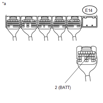
E14-2 (BATT) - Body ground |
Always |
11 to 14 V |
|
*a |
Rear view of wire harness connector (to ECM) |
| NG | |
REPAIR OR REPLACE HARNESS OR CONNECTOR (BATTERY - ECM) |
|
|
4. |
CHECK WHETHER DTC OUTPUT RECURS (DTC P056014) |
(a) Connect the Techstream to the DLC3.
(b) Turn the Ignition switch ON.
(c) Turn the Techstream on.
(d) Clear the DTCs (See page ).
(e) Turn the Ignition switch off and wait for at least 30 seconds.
(f) Turn the Ignition switch ON.
(g) Turn the Techstream on.
(h) Wait 5 seconds or more.
(i) Enter the following menus: Powertrain / Transmission / Trouble Codes.
(j) Read the DTCs using the Techstream.
Result:|
Result |
Proceed to |
|---|---|
|
DTC P056014 is output |
A |
|
DTC is not output |
B |
| A | |
REPLACE ECM |
| B | |
CHECK FOR INTERMITTENT PROBLEMS |
 Diagnostic Trouble Code Chart
DIAGNOSTIC TROUBLE CODE CHART
If a DTC is displayed during the DTC check, check the parts listed in
the table below and proceed to the "See page" given.
*1: "Comes on&qu ...
 Starter Relay Circuit Short to Battery (P061512)
DESCRIPTION
While the engine is being cranked, positive battery voltage is applied to terminal
STA of the ECM. If the ECM detects the starter control (STA) signal while the vehicle
is being drive ...
Other materials:
Parking Brake Lever
Components
COMPONENTS
ILLUSTRATION
ILLUSTRATION
Installation
INSTALLATION
PROCEDURE
1. INSTALL PARKING BRAKE SWITCH ASSEMBLY
2. INSTALL PARKING BRAKE LEVER SUB-ASSEMBLY
(a) Install the 2 toothed washers and parking brake lever support to the parking
brake lever.
(b) Install th ...
Open or Short in Front Speed Sensor RH Circuit (C1405,C1406)
DESCRIPTION
Refer to DTCs C1401 and C1402 (See page ).
DTC No.
Detection Item
DTC Detection Condition
Trouble Area
C1405
Open or Short in Front Speed Sensor RH Circuit
Either of the following is detected:
...
Main Body ECU Communication Stop Mode
DESCRIPTION
Detection Item
Symptom
Trouble Area
Main Body ECU Communication Stop Mode
Either condition is met:
Communication stop for "Main Body" is indicated on the "Communication
Bus Check" screen ...
