Toyota Tacoma (2015-2018) Service Manual: System Diagram
SYSTEM DIAGRAM
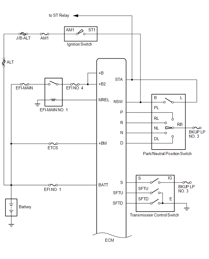
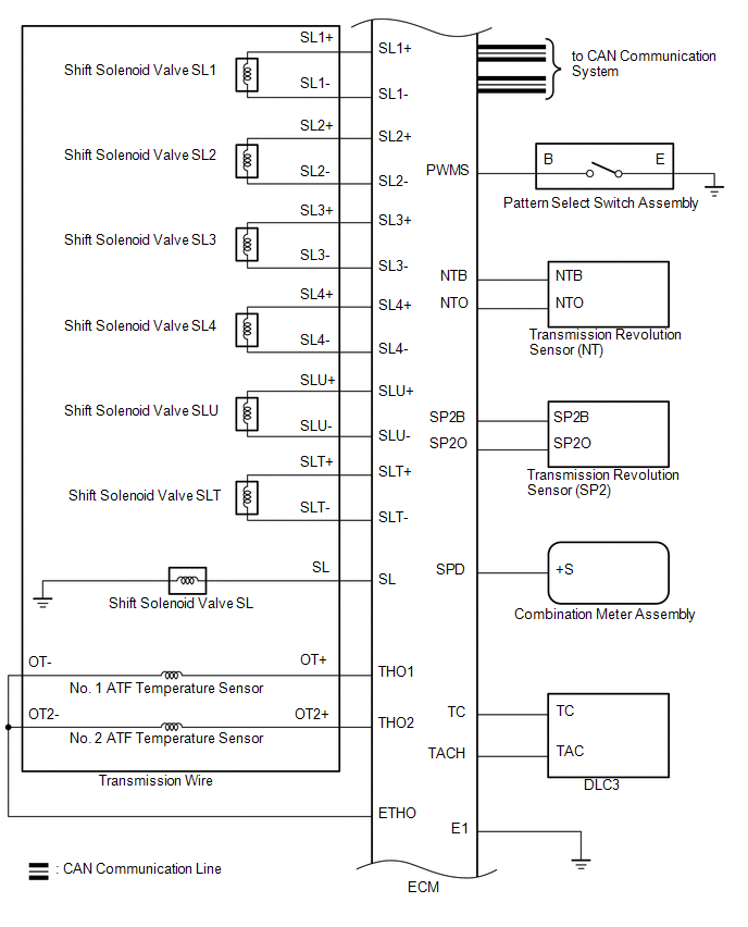
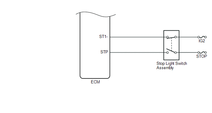
The configuration of the electronic control system in the AC60E automatic transmission is as shown in the following chart.
 System Description
SYSTEM DESCRIPTION
1. SYSTEM DESCRIPTION
(a) The Electronic Controlled Automatic Transmission (ECT) is an automatic transmission
that has its shift timing electronically controlled by the ECM. The ...
 Hydraulic Test
HYDRAULIC TEST
1. PERFORM HYDRAULIC TEST
(a) Measure the line pressure.
CAUTION:
The line pressure test should always be performed with at least 2 people. One
person should observe the condition ...
Other materials:
Removal
REMOVAL
PROCEDURE
1. REMOVE STEERING PAD
(See page
)
2. REMOVE STEERING WHEEL ASSEMBLY
3. REMOVE LOWER STEERING COLUMN COVER
4. REMOVE UPPER STEERING COLUMN COVER
5. REMOVE SPIRAL CABLE SUB-ASSEMBLY WITH SENSOR
(a) Slide the slider and disconnect the airbag connect ...
Malfunction of ID-BOX Recognition (B278D)
DESCRIPTION
When the certification ECU (smart key ECU assembly) detects an input signal indicating
that the vehicle is equipped with an ID code box even though the ID code box is
not registered, the certification ECU (smart key ECU assembly) stores this DTC.
DTC Code
DTC ...
Rear Speed Sensor RH Malfunction (C1403,C1404)
DESCRIPTION
The speed sensor detects wheel speed and sends the appropriate signals to the
skid control ECU (brake actuator assembly). These signals are used for brake control.
The speed sensor rotors have rows of alternating N and S magnetic poles and their
magnetic fields change when the roto ...
