Toyota Tacoma (2015-2018) Service Manual: System Diagram
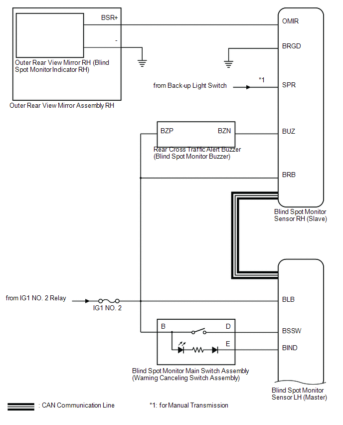
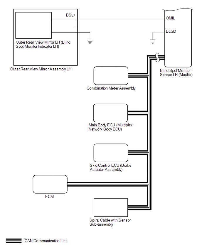
SYSTEM DIAGRAM
 System Description
SYSTEM DESCRIPTION
1. GENERAL
(a) The blind spot monitor system has the blind spot monitor function and rear
cross traffic alert function.
(1) Blind spot monitor function
The blind spot m ...
 How To Proceed With Troubleshooting
CAUTION / NOTICE / HINT
HINT:
Use the following procedure to troubleshoot the blind spot monitor system.
*: Use the Techstream.
PROCEDURE
1.
VEHICLE BRO ...
Other materials:
Communication Error from VSC to ECM Invalid Serial Data Received (P163081)
DESCRIPTION
The skid control ECU (master cylinder solenoid)*1 or skid control ECU (brake
actuator assembly)*2 sends signals such as cruise control cancel signals and brake
demand response signals to the ECM when the dynamic radar cruise control system
is operating.
DTC No.
...
Microphone Amplifier
Components
COMPONENTS
ILLUSTRATION
*A
w/o Sliding Roof
*B
w/ Sliding Roof
*1
TELEPHONE MICROPHONE ASSEMBLY
-
-
Removal
REMOVAL
PROCEDURE
1. REMOVE ROOF HEADLINING ASSEMBLY (for Double ...
Maintenance data (fuel, oil level, etc.)
Dimensions
2WD models except PreRunner
*: Unladen vehicle
4WD models and PreRunner (except
Regular Cab models)
*: Unladen vehicle
*: Unladen vehicle
Vehicle capacity weight
2WD models except PreRunner
*: Installing accessories in addition to those installed at the factory increase ...
