Toyota Tacoma (2015-2018) Service Manual: System Diagram
SYSTEM DIAGRAM
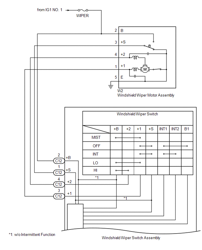
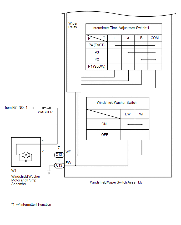
1. FRONT WIPER AND WASHER SYSTEM
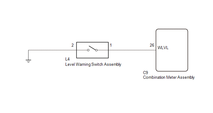
2. WASHER FLUID LEVEL WARNING SYSTEM
 Precaution
PRECAUTION
1. IGNITION SWITCH EXPRESSIONS
(a) The type of ignition switch used on this model differs depending on the specifications
of the vehicle. The expressions listed in the table below are u ...
 Operation Check
OPERATION CHECK
1. CHECK INTERMITTENT CONTROL FUNCTION (w/ Intermittent Time Adjustment Switch)
(a) Turn the ignition switch to ON.
(b) Turn the windshield wiper switch assembly to the INT position ...
Other materials:
System Description
SYSTEM DESCRIPTION
1. GENERAL
(a) The blind spot monitor system has the blind spot monitor function and rear
cross traffic alert function.
(1) Blind spot monitor function
The blind spot monitor function is a function that assists the driver
in making the decision to change lanes. Th ...
On-vehicle Inspection
ON-VEHICLE INSPECTION
PROCEDURE
1. INSPECT FRONT AXLE HUB BEARING
(a) Remove the front wheel.
(b) for 4WD:
(1) Remove the front axle hub grease cap (See page
).
(c) Remove the front disc brake caliper (See page
).
(d) Remove the front disc.
(e) Inspect the axle hub backlash.
(1) Usi ...
Switch Failure (B2342)
DESCRIPTION
This DTC is stored when the sliding roof ECU (sliding roof drive gear sub-assembly)
detects that the sliding roof switch is stuck for 30 seconds or more.
DTC No.
DTC Detection Condition
Trouble Area
B2342
Sliding roof ECU ( ...
