Toyota Tacoma (2015-2018) Service Manual: Washer Motor
Components
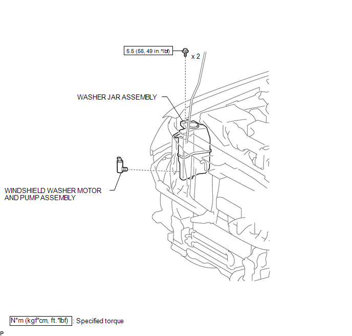
COMPONENTS
ILLUSTRATION
On-vehicle Inspection
ON-VEHICLE INSPECTION
PROCEDURE
1. INSPECT WINDSHIELD WASHER MOTOR AND PUMP ASSEMBLY
HINT:
This check should be performed with the windshield washer motor and pump assembly installed to the windshield washer jar assembly.
|
(a) With the windshield washer motor and pump assembly installed to the washer jar, pour windshield washer fluid into the washer jar. Text in Illustration
|
|
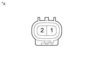
(b) Check that the windshield washer fluid is pumped when battery voltage is applied to the terminals.
:
|
Condition |
Specified Condition |
|---|---|
|
Battery positive (+) → Terminal 1 Battery negative (-) → Terminal 2 |
Washer fluid is pumped |
If the result is not as specified, replace the windshield washer motor and pump assembly.
Removal
REMOVAL
PROCEDURE
1. REMOVE HEADLIGHT ASSEMBLY RH
HINT:
Use the same procedure as for the LH side (See page
.gif) ).
).
2. SEPARATE WASHER JAR ASSEMBLY
|
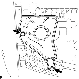
(a) Remove the 2 bolts to separate the washer jar assembly from the vehicle body. |
|
3. DRAIN WINDSHIELD WASHER FLUID
|
(a) Disconnect the washer hose from the windshield washer motor and pump assembly, and drain the windshield washer fluid. HINT: Use a container to collect the washer fluid. |
|
4. REMOVE WINDSHIELD WASHER MOTOR AND PUMP ASSEMBLY
|
(a) Disconnect the connector. |
|
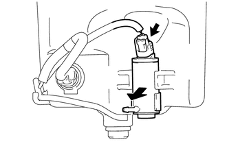
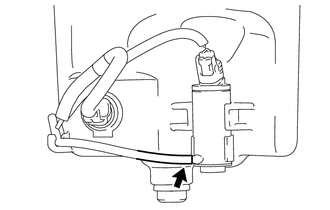
(b) Remove the windshield washer motor and pump assembly as shown in the illustration.
Installation
INSTALLATION
PROCEDURE
1. INSTALL WINDSHIELD WASHER MOTOR AND PUMP ASSEMBLY
|
(a) Install the windshield washer motor and pump assembly. |
|
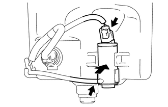
(b) Connect the washer hose.
(c) Connect the connector.
2. INSTALL WASHER JAR ASSEMBLY
|
(a) Install the windshield washer jar assembly with the 2 bolts in the order shown in the illustration. Torque: 5.5 N·m {56 kgf·cm, 49 in·lbf} |
|

3. ADD WASHER FLUID
(a) Add washer fluid to the washer jar assembly.
4. INSTALL HEADLIGHT ASSEMBLY RH
HINT:
Use the same procedure as for the LH side. (See page
.gif) )
)
 Washer Level Warning Switch
Components
COMPONENTS
ILLUSTRATION
Inspection
INSPECTION
PROCEDURE
1. INSPECT LEVEL WARNING SWITCH ASSEMBLY
HINT:
This check should be performed with the windshield washer motor and pump ...
 Washer Nozzle
Components
COMPONENTS
ILLUSTRATION
On-vehicle Inspection
ON-VEHICLE INSPECTION
PROCEDURE
1. INSPECT WASHER NOZZLE SUB-ASSEMBLY
(a) Operate the washer nozzle sub-assembly and check the pos ...
Other materials:
Short in Side Squib RH Circuit (B1820/55-B1823/55)
DESCRIPTION
The side squib RH circuit consists of the airbag sensor assembly and the front
seat airbag assembly RH.
The circuit signals the SRS to deploy when airbag deployment conditions are met.
These DTCs are set when a malfunction is detected in the side squib RH circuit.
DTC No ...
Torque Converter And Drive Plate
Inspection
INSPECTION
PROCEDURE
1. INSPECT TORQUE CONVERTER ASSEMBLY
(a) Inspect the one-way clutch.
(1) Press on the spline of the stator with a finger and rotate the spline. Check
that the spline rotates smoothly when turned clockwise and rotates with difficulty
when turned counterclock ...
Pattern Select Switch Power Mode Circuit
DESCRIPTION
The ECM memory contains the programs for the normal and PWR shift patterns.
By following the programs corresponding to the signals from the pattern select
switch assembly, park/neutral position switch and other various sensors, the ECM
switches the shift solenoid valves on and off, ...
