Toyota Tacoma (2015-2018) Service Manual: System Diagram
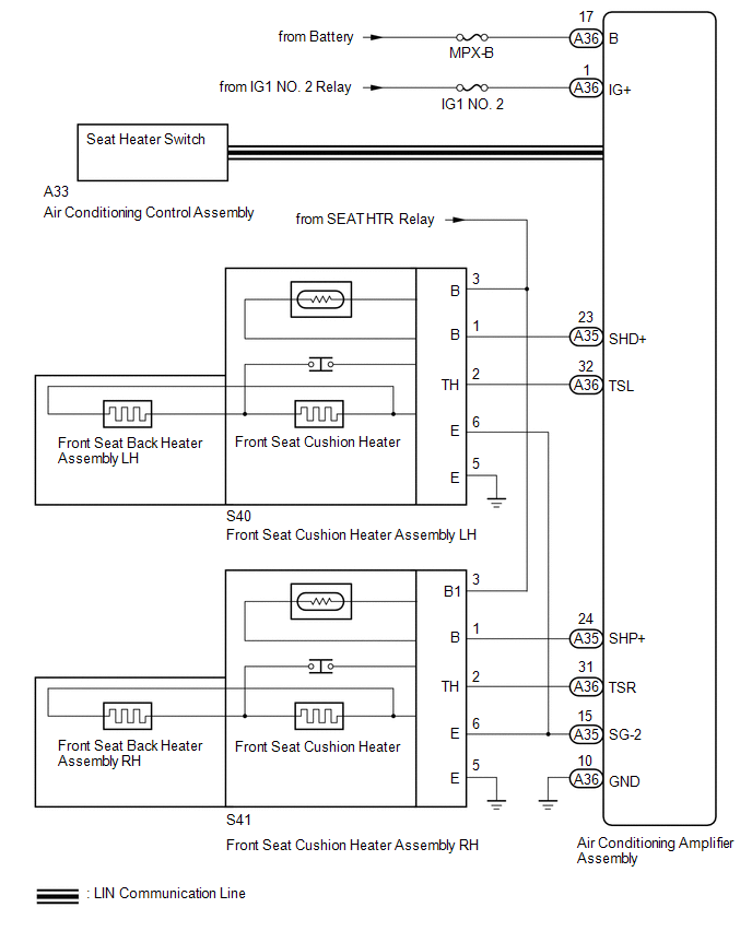
SYSTEM DIAGRAM
 Precaution
PRECAUTION
1. EXPRESSIONS OF IGNITION SWITCH
The type of ignition switch used on this model differs depending on the specifications
of the vehicle. The expressions listed in the table below are us ...
 How To Proceed With Troubleshooting
CAUTION / NOTICE / HINT
HINT:
Use this procedure to troubleshoot the seat heater system.
*: Use the Techstream.
PROCEDURE
1.
VEHICLE BROUGHT TO WORKSHOP
...
Other materials:
Removal
REMOVAL
PROCEDURE
1. REMOVE CLUTCH MASTER CYLINDER ASSEMBLY
(See page )
2. REMOVE TURN OVER SPRING SEAT COMPRESSION SPRING
(a) Remove the compression spring.
3. REMOVE CLUTCH PEDAL SUB-ASSEMBLY
(a) Remove the bolt and nut.
...
On-vehicle Inspection
ON-VEHICLE INSPECTION
PROCEDURE
1. INSPECT DRIVE BELT
(a) Visually check the belt for defects, such as excessive wear and frayed cords.
If any defects are found, replace the drive belt.
HINT:
Replace the belt if there are any missing ribs.
2. BLEED POWER STEERING SYSTEM
(a) Check the fluid ...
No Answer-Back
DESCRIPTION
In some cases, wireless door lock control functions are normal but the hazard
warning light and/or wireless door lock buzzer answer-back function(s) does not
operate. In such cases, hazard warning light and wireless door lock buzzer signal
outputs from the main body ECU (multiplex ...
