Toyota Tacoma (2015-2018) Service Manual: System Diagram
SYSTEM DIAGRAM
 System Description
SYSTEM DESCRIPTION
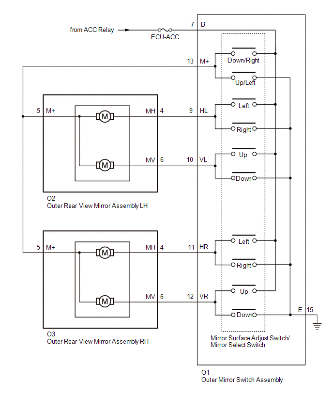
1. FUNCTION OF MAIN COMPONENTS
Component
Function
Vertical mirror motor
Moves the mirror surface vertically in accordance with th ...
 Operation Check
OPERATION CHECK
1. CHECK REMOTE CONTROL MIRROR FUNCTION
(a) Turn the ignition switch to ON.
(b) With L on the mirror select switch selected, check that the outer rear view
mirror assembly LH surf ...
Other materials:
Dtc Check / Clear
DTC CHECK / CLEAR
1. CHECK DTC
(a) Connect the Techstream to the DLC3.
(b) Turn the ignition switch to ON.
(c) Turn the Techstream on.
(d) Enter the following menus: Powertrain / Engine / Trouble Codes.
(e) Check for DTCs, and then write them down.
(f) Check the details of the DTCs (See page ...
Lost Communication with ECM / PCM "A" (U0100,U0126,U0129,U0142)
DESCRIPTION
These DTCs are stored if there is a malfunction in the CAN communication system
connected to the blind spot monitor sensor.
HINT:
If CAN communication system DTCs are stored, they may also be stored for other
systems.
DTC Code
DTC Detection Condition
...
Front Radar Sensor (C1A10)
DESCRIPTION
When an internal malfunction is detected in the millimeter wave radar sensor
assembly, DTC C1A10 is stored.
DTC No.
Detection Item
DTC Detection Condition
Trouble Area
C1A10
Front Radar Sensor
When the ...
