Toyota Tacoma (2015-2018) Service Manual: System Diagram
SYSTEM DIAGRAM
 System Description
SYSTEM DESCRIPTION
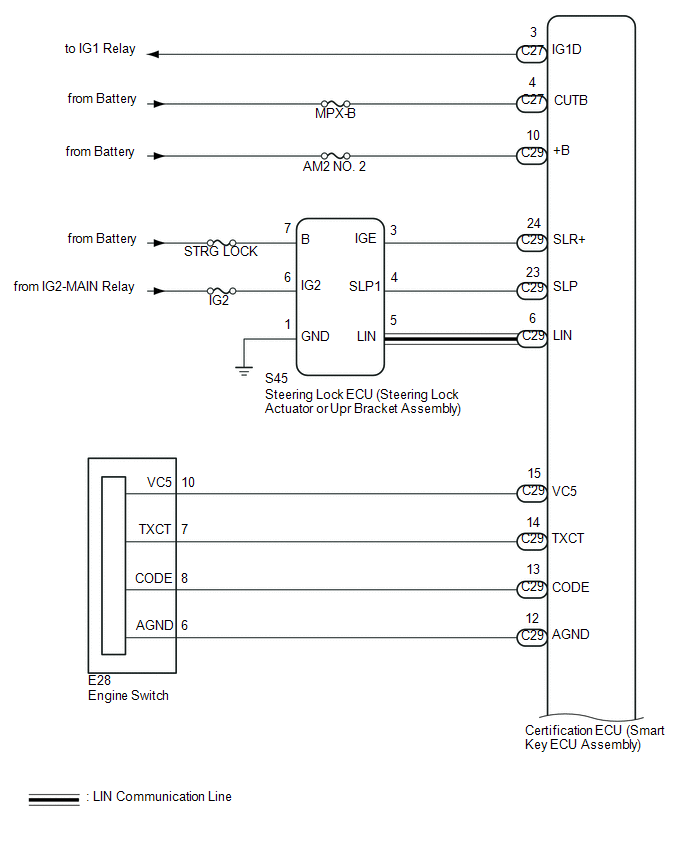
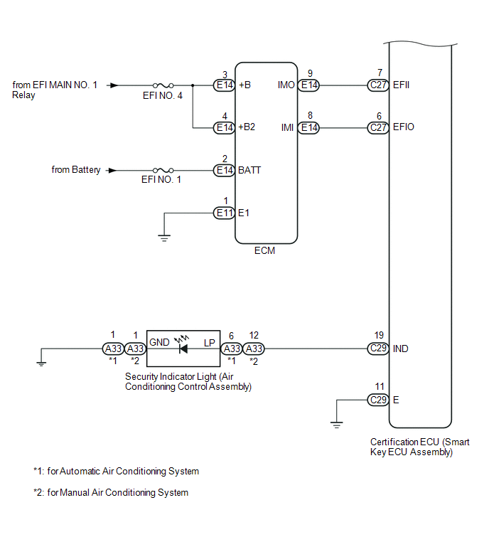
1. ENGINE IMMOBILISER SYSTEM DESCRIPTION
(a) The engine immobiliser system determines whether or not to enable starting
of the SFI system based on a comparison of the key ID cod ...
 How To Proceed With Troubleshooting
CAUTION / NOTICE / HINT
HINT:
Use this procedure to troubleshoot the engine immobiliser system.
*: Use the Techstream.
PROCEDURE
1.
VEHICLE BROUGHT TO W ...
Other materials:
Heater Circuit (C1AAE)
DESCRIPTION
If the forward recognition camera detects a malfunction in the camera heater
(forward recognition hood) circuit, it will output a malfunction signal to the millimeter
wave radar sensor assembly via CAN communication and DTC C1AAE will be stored.
DTC No.
Detect ...
ECU Power Source Circuit
DESCRIPTION
The IG circuit is the power source for the tire pressure warning ECU and receiver.
WIRING DIAGRAM
CAUTION / NOTICE / HINT
NOTICE:
When replacing the tire pressure warning ECU and receiver, read the
transmitter IDs stored in the old ECU using the Techstream and write th ...
How To Proceed With Troubleshooting
CAUTION / NOTICE / HINT
HINT:
Use the following procedure to troubleshoot the power mirror control
system.
*: Use the Techstream.
PROCEDURE
1.
VEHICLE BROUGHT TO WORKSHOP
NEXT
...
