Toyota Tacoma (2015-2018) Service Manual: Sliding Roof Switch Assembly
Components
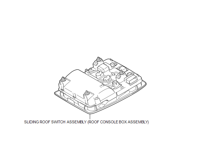
COMPONENTS
ILLUSTRATION
Installation
INSTALLATION
PROCEDURE
1. INSTALL SLIDING ROOF SWITCH ASSEMBLY (ROOF CONSOLE BOX ASSEMBLY)
(a) Connect the connector.
(b) Engage the 4 clips to install the sliding roof switch assembly (roof console box assembly).
Removal
REMOVAL
PROCEDURE
1. REMOVE SLIDING ROOF SWITCH ASSEMBLY (ROOF CONSOLE BOX ASSEMBLY)
|
(a) Using a moulding remover D, disengage the 4 clips to separate the sliding roof switch assembly (roof console box assembly). |
|
.png)
(b) Disconnect the connector to remove the sliding roof switch assembly (roof console box assembly).
 Removal
REMOVAL
PROCEDURE
1. REMOVE SLIDING ROOF SIDE GARNISH LH
(a) Fully open the sunshade trim sub-assembly.
(b) Remove the sliding roof side garnish LH.
...

Other materials:
Removal
REMOVAL
PROCEDURE
1. PRECAUTION
CAUTION:
Be sure to read Precaution thoroughly before servicing (See page
).
NOTICE:
After turning the ignition switch off, waiting time may be required before disconnecting
the cable from the negative (-) battery terminal. Therefore, make sure to read the
...
Driver Side Power Window does not Operate with Power Window Master Switch
DESCRIPTION
When the engine is running or the ignition switch is ON, the front power window
regulator motor assembly LH is operated by the power window regulator master switch
assembly. The front power window regulator motor assembly LH has motor, regulator,
and ECU functions.
HINT:
If the ...
Four Wheel Drive (4WD) Low Switch Circuit Range / Performance (P2772)
DESCRIPTION
This DTC is output when a malfunction in the L4 detection switch is detected.
DTC No.
Detection Item
DTC Detection Condition
Trouble Area
P2772
Four Wheel Drive (4WD) Low Switch Circuit Range / Performance
...
