Toyota Tacoma (2015-2018) Service Manual: Parts Location
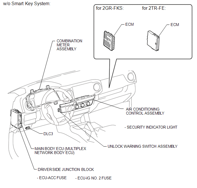
PARTS LOCATION
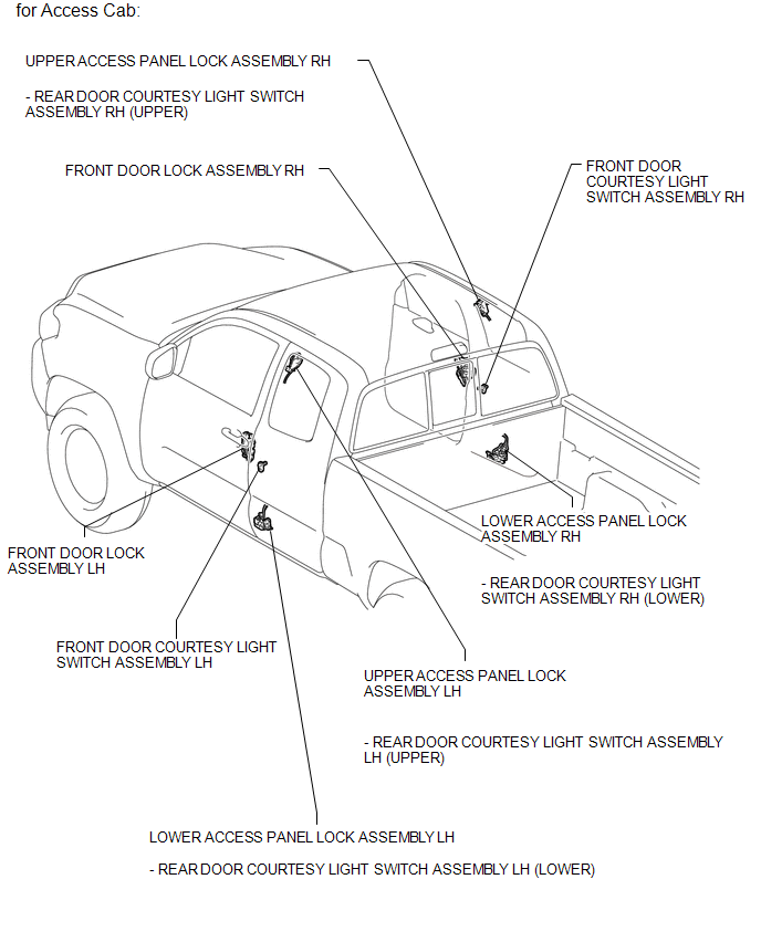
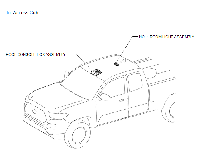
ILLUSTRATION
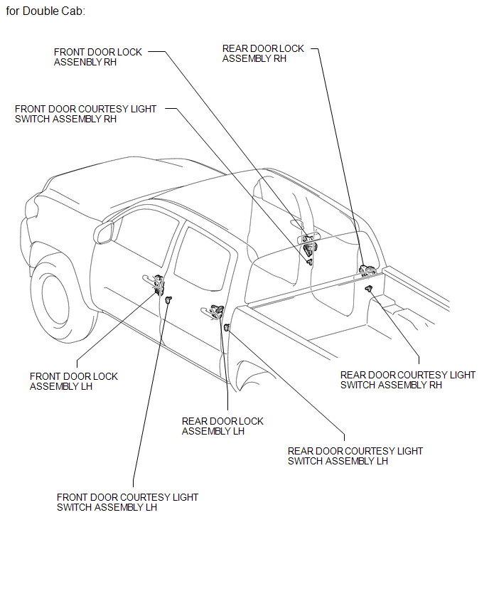
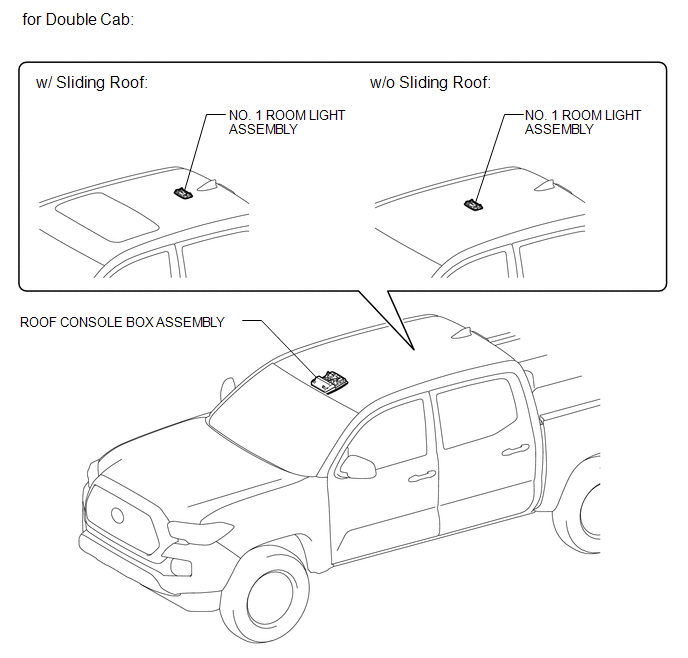
ILLUSTRATION
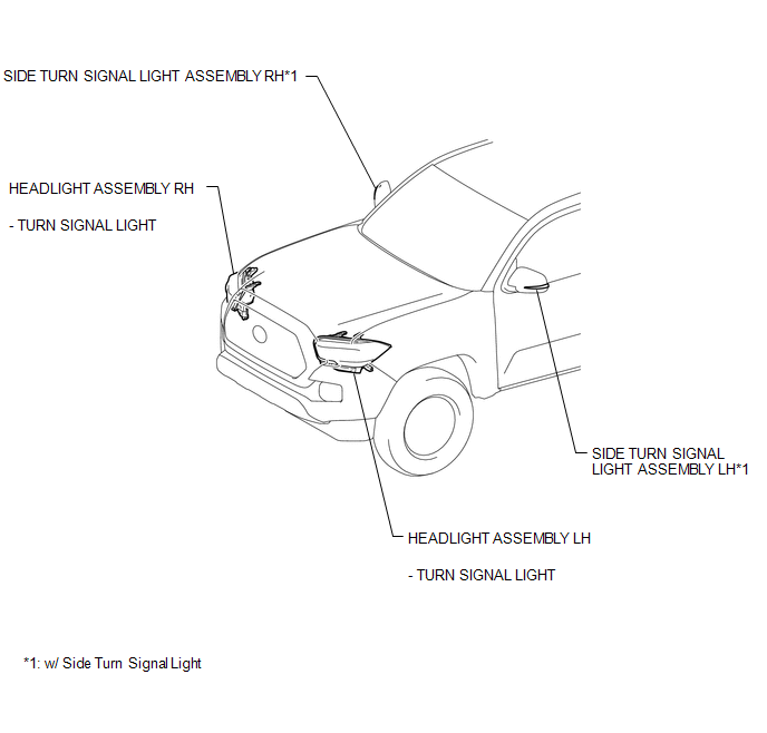
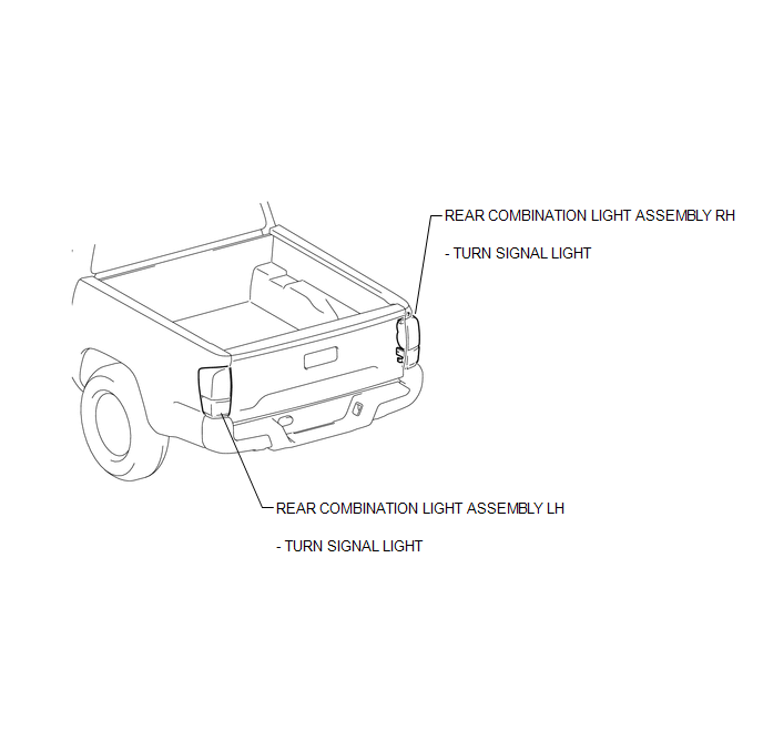
ILLUSTRATION
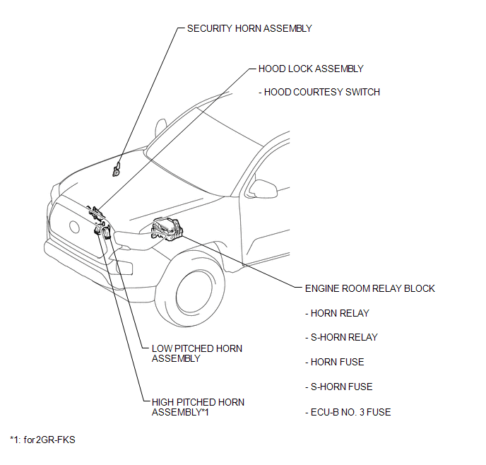
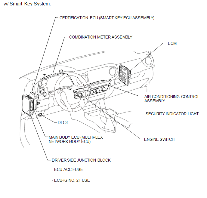
ILLUSTRATION
ILLUSTRATION
ILLUSTRATION
ILLUSTRATION
ILLUSTRATION
ILLUSTRATION

 Precaution
PRECAUTION
1. IGNITION SWITCH EXPRESSIONS
(a) The type of ignition switch used on this model differs according to the specifications
of the vehicle. The expressions listed in the table below are u ...
Other materials:
Confirm Cellular Phone Functionality
PROCEDURE
1.
CHECK CUSTOMER'S CELLULAR PHONE COMPATIBILITY
(a) Check if the cellular phone is compatible (Refer to http://www.toyota.com/entune/).
Result
Result
Proceed to
Cellular phone is compatible
A
...
Lost Communication with ECM / PCM "A" (U0100,U0104,U0122,U0125,U0126,U0129)
DESCRIPTION
The millimeter wave radar sensor assembly and ECM communicate with each sensor
and ECU via CAN communication.
If any malfunction is detected in a CAN communication circuit, one or more CAN
communication system DTCs are stored.
DTC No.
Detection Item
...
SRS airbag instructions for Canadian owners (in French)
The following is a French explanation of SRS airbag instructions extracted
from the SRS airbag section in this manual.
See the SRS airbag section for more detailed SRS airbag instructions in English.
...
