Toyota Tacoma (2015-2018) Service Manual: Short to +B in Buzzer (C1ABD,C1ABE)
DESCRIPTION
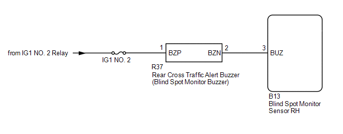
- DTC C1ABD is stored when the blind spot monitor sensor RH detects a +B short in rear cross traffic alert buzzer (blind spot monitor buzzer) circuit.
- DTC C1ABE is stored when the blind spot monitor sensor RH detects a ground short or open in rear cross traffic alert buzzer (blind spot monitor buzzer) circuit.
|
DTC Code |
DTC Detection Condition |
Trouble Area |
|---|---|---|
|
C1ABD |
|
|
|
C1ABE |
|
|
WIRING DIAGRAM
CAUTION / NOTICE / HINT
NOTICE:
- When checking for DTCs, make sure that the blind spot main switch assembly (warning canceling switch assembly) is on.
- Inspect the fuses for circuits related to this system before performing the following inspection procedure.
PROCEDURE
|
1. |
CHECK DTC |
(a) Clear the DTCs (See page .gif) ).
).
(b) Recheck for DTCs and check if the same DTC is output again (See page
).
OK:
No DTCs are output.
| OK | .gif) |
USE SIMULATION METHOD TO CHECK |
|
.gif)
|
2. |
CHECK HARNESS AND CONNECTOR (REAR CROSS TRAFFIC ALERT BUZZER - BATTERY AND BLIND SPOT MONITOR SENSOR RH) |
(a) Disconnect the R37 rear cross traffic alert buzzer (blind spot monitor buzzer) connector.
(b) Disconnect the B13 blind spot monitor sensor RH connector.
(c) Measure the resistance according to the value(s) in the table below.
Standard Resistance:
|
Tester Connection |
Condition |
Specified Condition |
|---|---|---|
|
R37-2 (BZN) - B13-3 (BUS) |
Always |
Below 1 Ω |
|
R37-2 (BZN) - Body ground |
Always |
10 kΩ or higher |
(d) Measure the voltage according to the value(s) in the table below.
Standard Voltage:
|
Tester Connection |
Switch Condition |
Specified Condition |
|---|---|---|
|
R37-1 (BZP) - Body ground |
Ignition switch ON |
11 to 14 V |
|
R37-1 (BZP) - Body ground |
Ignition switch off |
Below 1 V |
| NG | |
REPAIR OR REPLACE HARNESS OR CONNECTOR |
|
|
3. |
REPLACE BLIND SPOT MONITOR BUZZER (REAR CROSS TRAFFIC ALERT BUZZER) |
(a) Replace the rear cross traffic alert buzzer (blind spot monitor buzzer) with a new or normally functioning one.
- for Access Cab:
- for Double Cab:
|
|
4. |
CHECK DTC |
(a) Clear the DTCs (See page ).
(b) Recheck for DTCs and check if the same DTC is output again (See page
).
OK:
No DTCs are output.
| OK | |
END (REAR CROSS TRAFFIC ALERT BUZZER (BLIND SPOT MONITOR BUZZER) WAS DEFECTIVE) |
| NG | |
REPLACE BLIND SPOT MONITOR SENSOR RH |
 Lost Communication with ECM / PCM "A" (U0100,U0126,U0129,U0142)
DESCRIPTION
These DTCs are stored if there is a malfunction in the CAN communication system
connected to the blind spot monitor sensor.
HINT:
If CAN communication system DTCs are stored, they may ...
 Blind Spot Monitor Slave Module Beam Axis Inspection Incomplete (C1ABC)
DESCRIPTION
This DTC is stored when a beam axis inspection has not been performed for the
blind spot monitor sensor RH.
HINT:
This DTC is always stored after replacing a blind spot monitor sensor ...
Other materials:
Rear Occupant Classification Sensor RH Circuit Malfunction (B1783)
DESCRIPTION
The rear occupant classification sensor RH circuit consists of the occupant detection
ECU and the rear occupant classification sensor RH.
DTC B1783 is set when a malfunction is detected in the rear occupant classification
sensor RH circuit.
DTC No.
DTC Detect ...
Personal Light Assembly
Components
COMPONENTS
ILLUSTRATION
Installation
INSTALLATION
PROCEDURE
1. INSTALL MAP LIGHT BULB
(a) Install the 2 map light bulbs to the 2 map light sockets.
(b) Turn the 2 map light sockets with 2 map light bulbs in the direction
indicated by the arrow shown in the ill ...
Unable to Unlock Steering Wheel (Engine cannot Start)
DESCRIPTION
The steering lock actuator assembly activates the steering lock motor and moves
the lock bar into the steering column to lock the steering.
The steering may not unlock when the lock bar gets stuck in the lock hole of
the steering column. In this case, if the engine switch is turned ...
