Toyota Tacoma (2015-2018) Service Manual: Short in Front Passenger Side Squib Circuit (B1805/52-B1808/52)
DESCRIPTION
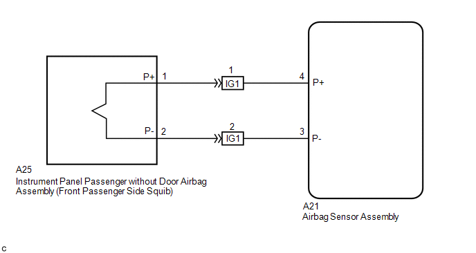
The front passenger side squib circuit consists of the airbag sensor assembly and the instrument panel passenger without door airbag assembly.
The circuit instructs the SRS to deploy when deployment conditions are met.
These DTCs are recorded when a malfunction is detected in the front passenger side squib circuit.
|
DTC No. |
DTC Detection Condition |
Trouble Area |
|---|---|---|
|
B1805/52 |
|
|
|
B1806/52 |
|
|
|
B1807/52 |
|
|
|
B1808/52 |
|
|
WIRING DIAGRAM
CAUTION / NOTICE / HINT
NOTICE:
After turning the ignition switch off, waiting time may be required before disconnecting
the cable from the negative (-) battery terminal. Therefore, make sure to read the
disconnecting the cable from the negative (-) battery terminal notices before proceeding
with work (See page .gif) ).
).
HINT:
- Perform the simulation method by selecting check mode (Signal Check)
using the Techstream (See page ).
- After selecting check mode (Signal Check), perform the simulation method
by wiggling each connector of the airbag system or driving the vehicle on
a city road or rough road (See page
).
PROCEDURE
|
1. |
CHECK DTC |
(a) Proceed to the appropriate step according to DTC readings.
(1) If using the Techstream (read the 5-digit DTCs): Using the Techstream, check
for DTCs (See page ).
|
Result |
Proceed to |
|---|---|
|
DTC B1805 is output. |
A |
|
DTC B1806 is output. |
B |
|
DTC B1807 is output. |
C |
|
DTC B1808 is output. |
D |
| B | .gif) |
GO TO STEP 7 |
| C | |
GO TO STEP 11 |
| D | |
GO TO STEP 15 |
|
.gif)
|
2. |
CHECK CONNECTOR |
(a) Turn the ignition switch off.
(b) Disconnect the negative (-) terminal cable from the battery, and wait for at least 90 seconds.
(c) Check that the instrument panel wire assembly connectors (on the instrument panel passenger without door airbag assembly side) are not damaged.
OK:
The lock button is not disengaged, and the claw of the lock is not deformed or damaged.
| NG | |
REPLACE INSTRUMENT PANEL WIRE ASSEMBLY |
|
|
3. |
CHECK CONNECTION OF CONNECTORS |
(a) Check that the connectors are properly connected to the airbag sensor assembly and the instrument panel wire assembly.
OK:
The connectors are properly connected.
| NG | |
CONNECT CONNECTORS |
|
|
4. |
CHECK INSTRUMENT PANEL WIRE ASSEMBLY (FOR SHORT) |
|
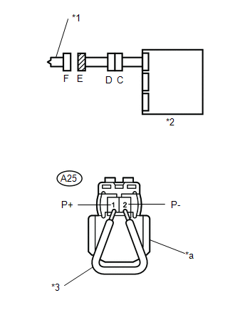
(a) Disconnect the instrument panel wire assembly connectors from the instrument panel wire and instrument panel passenger without door airbag assembly. |
|
(b) Release the activation prevention mechanism built into connector D (See page
).
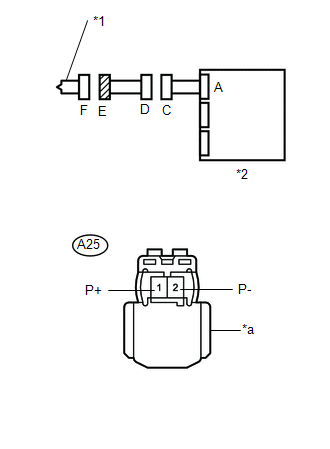
(c) Measure the resistance according to the value(s) in the table below.
Standard Resistance:
|
Tester Connection |
Condition |
Specified Condition |
|---|---|---|
|
A25-1 (P+) - A25-2 (P-) |
Always |
1 MΩ or Higher |
|
*1 |
Front Passenger Side Squib |
|
*2 |
Airbag Sensor Assembly |
|
*a |
Color: Orange |
| NG | |
REPLACE INSTRUMENT PANEL WIRE ASSEMBLY |
|
|
5. |
CHECK INSTRUMENT PANEL WIRE (FOR SHORT) |
|
(a) Disconnect the instrument panel wire connector from the airbag sensor assembly. |
|
(b) Release the activation prevention mechanism built into connector B (See page
).
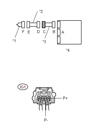
(c) Measure the resistance according to the value(s) in the table below.
Standard Resistance:
|
Tester Connection |
Condition |
Specified Condition |
|---|---|---|
|
IG1-1 (P+) - IG1-2 (P-) |
Always |
1 MΩ or Higher |
|
*1 |
Front Passenger Side Squib |
|
*2 |
Instrument Panel Wire Assembly |
|
*3 |
Instrument Panel Wire |
|
*4 |
Airbag Sensor Assembly |
| NG | |
REPLACE INSTRUMENT PANEL WIRE |
|
|
6. |
CHECK AIRBAG SENSOR ASSEMBLY |
|
(a) Connect the instrument panel wire connectors to the airbag sensor assembly and instrument panel wire assembly. |
|
(b) Connect the negative (-) terminal cable to the battery, and wait for at least 2 seconds.
(c) Turn the ignition switch to ON, and wait for at least 60 seconds.
(d) Clear any DTCs stored in the memory (See page
).
(e) Turn the ignition switch off.
(f) Turn the ignition switch to ON, and wait for at least 60 seconds.
(g) Check for DTCs (See page ).
OK:
DTC B1805 is not output.
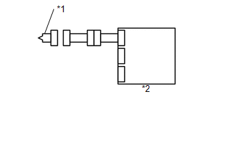
Text in Illustration|
*1 |
Front Passenger Side Squib |
|
*2 |
Airbag Sensor Assembly |
HINT:
DTCs other than B1805 may be output at this time, but they are not related to this check.
Result|
Result |
Proceed to |
|---|---|
|
NG |
A |
|
OK |
B |
| A | |
REPLACE AIRBAG SENSOR ASSEMBLY |
| B | |
GO TO STEP 20 |
|
7. |
CHECK CONNECTOR |
(a) Turn the ignition switch off.
(b) Disconnect the negative (-) terminal cable from the battery, and wait for at least 90 seconds.
(c) Check that the instrument panel wire assembly connectors (on the instrument panel passenger without door airbag assembly side) are not damaged.
OK:
The lock button is not disengaged, or the claw of the lock is not deformed or damaged.
| NG | |
REPLACE INSTRUMENT PANEL WIRE ASSEMBLY |
|
|
8. |
CHECK CONNECTORS |
(a) Check that the connectors are properly connected to the airbag sensor assembly and the instrument panel wire assembly.
OK:
The connectors are properly connected.
| NG | |
CONNECT CONNECTORS |
|
|
9. |
CHECK INSTRUMENT PANEL WIRE ASSEMBLY (FOR OPEN) |
|
(a) Disconnect the instrument panel wire assembly connectors from the instrument panel wire and instrument panel passenger without door airbag assembly. |
|
(b) Measure the resistance according to the value(s) in the table below.
Standard Resistance:
|
Tester Connection |
Condition |
Specified Condition |
|---|---|---|
|
A25-1 (P+) - A25-2(P-) |
Always |
Below 1 Ω |
|
*1 |
Front Passenger Side Squib |
|
*2 |
Airbag Sensor Assembly |
|
*a |
Color: Orange |
| MG | |
REPLACE INSTRUMENT PANEL WIRE ASSEMBLY |
|
|
10. |
CHECK INSTRUMENT PANEL WIRE (FOR OPEN) |
|
(a) Disconnect the instrument panel wire connector from the airbag sensor assembly. |
|
(b) Measure the resistance according to the value(s) in the table below.
Standard Resistance:
|
Tester Connection |
Condition |
Specified Condition |
|---|---|---|
|
IG1-1 (P+) - IG1-2 (P-) |
Always |
Below 1 Ω |
|
*1 |
Front Passenger Side Squib |
|
*2 |
Instrument Panel Wire Assembly |
|
*3 |
Instrument Panel Wire |
|
*4 |
Airbag Sensor Assembly |
|
Result |
Proceed to |
|---|---|
|
NG |
A |
|
OK |
B |
| A | |
REPLACE INSTRUMENT PANEL WIRE |
| B | |
GO TO STEP 19 |
|
11. |
CHECK CONNECTOR |
(a) Turn the ignition switch off.
(b) Disconnect the negative (-) terminal cable from the battery, and wait for at least 90 seconds.
(c) Check that the instrument panel wire assembly connectors (on the instrument panel passenger without door airbag assembly side) are not damaged.
OK:
The lock button is not disengaged, and the claw of the lock is not deformed or damaged.
| NG | |
REPLACE INSTRUMENT PANEL WIRE ASSEMBLY |
|
|
12. |
CHECK CONNECTION OF CONNECTORS |
(a) Check that the connectors are properly connected to the airbag sensor assembly and the instrument panel wire assembly.
OK:
The connectors are properly connected.
| NG | |
CONNECT CONNECTORS |
|
|
13. |
CHECK INSTRUMENT PANEL WIRE ASSEMBLY (TO GROUND) |
|
(a) Disconnect the instrument panel wire assembly connectors from the instrument panel wire and instrument panel passenger without door airbag assembly. |
|
(b) Measure the resistance according to the value(s) in the table below.
Standard Resistance:
|
Tester Connection |
Condition |
Specified Condition |
|---|---|---|
|
A25-1 (P+) - Body ground |
Always |
1 MΩ or Higher |
|
A25-2(P-) - Body ground |
Always |
1 MΩ or Higher |
|
*1 |
Front Passenger Side Squib |
|
*2 |
Airbag Sensor Assembly |
|
*a |
Color: Orange |
| NG | |
REPLACE INSTRUMENT PANEL WIRE ASSEMBLY |
|
|
14. |
CHECK INSTRUMENT PANEL WIRE (TO GROUND) |
|
(a) Disconnect the instrument panel wire connector from the airbag sensor assembly. |
|
(b) Measure the resistance according to the value(s) in the table below.
Standard Resistance:
|
Tester Connection |
Condition |
Specified Condition |
|---|---|---|
|
IG1-1 (P+) - Body ground |
Always |
1 MΩ or Higher |
|
IG1-2 (P-) - Body ground |
Always |
1 MΩ or Higher |
|
*1 |
Front Passenger Side Squib |
|
*2 |
Instrument Panel Wire Assembly |
|
*3 |
Instrument Panel Wire |
|
*4 |
Airbag Sensor Assembly |
|
Result |
Proceed to |
|---|---|
|
NG |
A |
|
OK |
B |
| A | |
REPLACE INSTRUMENT PANEL WIRE |
| B | |
GO TO STEP 19 |
|
15. |
CHECK CONNECTOR |
(a) Turn the ignition switch off.
(b) Disconnect the negative (-) terminal cable from the battery, and wait for at least 90 seconds.
(c) Check that the instrument panel wire assembly connectors (on the instrument panel passenger without door airbag assembly side) are not damaged.
OK:
The lock button is not disengaged, and the claw of the lock is not deformed or damaged.
| NG | |
REPLACE INSTRUMENT PANEL WIRE ASSEMBLY |
|
|
16. |
CHECK CONNECTION OF CONNECTORS |
(a) Check that the connectors are properly connected to the airbag sensor assembly and the instrument panel wire assembly.
OK:
The connectors are properly connected.
| NG | |
CONNECT CONNECTORS |
|
|
17. |
CHECK INSTRUMENT PANEL WIRE ASSEMBLY (TO B+) |
|
(a) Disconnect the instrument panel wire assembly connectors from the instrument panel wire and instrument panel passenger without door airbag assembly. |
|
(b) Connect the negative (-) terminal cable to the battery, and wait for at least 2 seconds.
(c) Turn the ignition switch to ON.
(d) Measure the voltage according to the value(s) in the table below.
Standard Voltage:
|
Tester Connection |
Switch Condition |
Specified Condition |
|---|---|---|
|
A25-1 (P+) - Body ground |
Ignition switch ON |
Below 1 V |
|
A25-2(P-) - Body ground |
Ignition switch ON |
Below 1 V |
|
*1 |
Front Passenger Side Squib |
|
*2 |
Airbag Sensor Assembly |
|
*a |
Color: Orange |
| NG | |
REPLACE INSTRUMENT PANEL WIRE ASSEMBLY |
|
|
18. |
CHECK INSTRUMENT PANEL WIRE (TO B+) |
|
(a) Turn the ignition switch off. |
|
(b) Disconnect the negative (-) terminal cable from the battery, and wait for at least 90 seconds.
(c) Disconnect the instrument panel wire connector from the airbag sensor assembly.
(d) Connect the negative (-) terminal cable to the battery, and wait for at least 2 seconds.
(e) Turn the ignition switch to ON.
(f) Measure the voltage according to the value(s) in the table below.
Standard Voltage:
|
Tester Connection |
Switch Condition |
Specified Condition |
|---|---|---|
|
IG1-1 (P+) - Body ground |
Ignition switch ON |
Below 1 V |
|
IG1-2 (P-) - Body ground |
Ignition switch ON |
Below 1 V |
|
*1 |
Front Passenger Side Squib |
|
*2 |
Instrument Panel Wire Assembly |
|
*3 |
Instrument Panel Wire |
|
*4 |
Airbag Sensor Assembly |
| NG | |
REPLACE INSTRUMENT PANEL WIRE |
|
|
19. |
CHECK AIRBAG SENSOR ASSEMBLY |
HINT:
If continuing from step 18, begin from (a). If continuing from any other step, begin from (c).
(a) Turn the ignition switch off.
(b) Disconnect the negative (-) terminal cable from the battery, and wait for at least 90 seconds.
(c) Connect the connectors to the airbag sensor assembly.
(d) Using a service wire, connect A25-1 (P+) and A25-2 (P-) of connector E.
NOTICE:
- Twist the end of the service wire in order to insert it into the connector.
- Do not forcibly insert the twisted service wire into the terminals of the connector when connecting.
(e) Connect the negative (-) terminal cable to the battery, and wait for at least 2 seconds.
(f) Turn the ignition switch to ON, and wait for at least 60 seconds.
(g) Clear any DTCs stored in the memory (See page
).
(h) Turn the ignition switch off.
(i) Turn the ignition switch to ON, and wait for at least 60 seconds.
(j) Check for DTCs (See page ).
OK:
DTC B1806, B1807 and B1808 are not output.
Text in Illustration|
*1 |
Front Passenger Side Squib |
|
*2 |
Airbag Sensor Assembly |
|
*3 |
Service Wire |
|
*a |
Color: Orange |
HINT:
DTCs other than B1806, B1807 or B1808 may be output at this time, but they are not related to this check.
| NG | |
REPLACE AIRBAG SENSOR ASSEMBLY |
|
|
20. |
CHECK INSTRUMENT PANEL PASSENGER WITHOUT DOOR AIRBAG ASSEMBLY (FRONT PASSENGER SIDE SQUIB) |
.png)
HINT:
If continuing from step 19, begin from (c). If continuing from any other step, being from (a).
(a) Turn the ignition switch off.
(b) Disconnect the negative (-) terminal cable from the battery, and wait for at least 90 seconds.
(c) Disconnect the service wire from connector C.
(d) Connect the connectors to the instrument panel passenger without door airbag assembly.
(e) Connect the negative (-) terminal cable to the battery, and wait for at least 2 seconds.
(f) Turn the ignition switch to ON, and wait for at least 60 seconds.
(g) Clear any DTCs stored in the memory (See page
).
(h) Turn the ignition switch off.
(i) Turn the ignition switch to ON, and wait for at least 60 seconds.
(j) Check for DTCs (See page ).
OK:
DTCs B1805, B1806, B1807 and B1808 are not output.
Text in Illustration|
*1 |
Front Passenger Side Squib |
|
*2 |
Airbag Sensor Assembly |
HINT:
DTCs other than B1805, B1806, B1807 or B1808 may be output at this time, but they are not related to this check.
| OK | |
USE SIMULATION METHOD TO CHECK |
| NG | |
REPLACE INSTRUMENT PANEL PASSENGER WITHOUT DOOR AIRBAG ASSEMBLY |
 Short in Front Passenger Side Knee Airbag Squib Circuit (B1865/65-B1868/65)
DESCRIPTION
The passenger side knee airbag squib circuit consists of the airbag sensor assembly
and lower No. 2 instrument panel airbag assembly.
The airbag sensor assembly uses this circuit to de ...
 Short in Driver Side Squib 2nd Step Circuit (B1810/53-B1813/53)
DESCRIPTION
The driver side squib 2nd step circuit consists of the airbag sensor assembly,
the spiral cable with sensor sub-assembly and the horn button assembly.
The circuit signals the SRS to de ...
Other materials:
Precaution
PRECAUTION
1. CAUTION REGARDING INTERFERENCE WITH ELECTRONIC DEVICES
CAUTION:
People with implantable cardiac pacemakers, cardiac resynchronization
therapy-pacemakers or implantable cardioverter defibrillators should keep
away from the smart key system antennas. The radio waves ma ...
Dtc Check / Clear
DTC CHECK / CLEAR
1. CHECK DTC
(a) Connect the Techstream to the DLC3.
(b) Turn the ignition switch to ON.
(c) Turn the Techstream on.
(d) Enter the following menus: Body Electrical / (desired system) / Trouble Codes.
(e) Check the details of the DTC(s) (See page
).
2. CLEAR DTC
(a) Connec ...
Front Airbag Sensor LH Circuit Malfunction (B1615/14)
DESCRIPTION
The front airbag sensor LH consists of parts such as the diagnostic circuit and
the frontal detection sensor.
When the airbag sensor assembly receives signals from the frontal deceleration
sensor, it determines whether or not the SRS should be activated.
DTC B1615/14 is set when a ...
