Toyota Tacoma (2015-2018) Service Manual: Repair
REPAIR
PROCEDURE
1. REPAIR INTAKE VALVE SEATS
NOTICE:
- Repair the intake valve seat while checking the seating position.
- Keep the lip free of foreign matter.
|
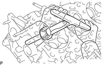
(a) Using a 45° cutter, resurface the valve seat so that the valve seat width is more than the specification. |
|
|
(b) Using 30° and 60° cutters, correct the valve seat so that the intake valve contacts the entire circumference of the seat. The contact should be in the center of the intake valve seat, and the intake valve seat width should be maintained within the specified range around the entire circumference of the intake valve seat. Text in Illustration
Standard width: 1.1 to 1.5 mm (0.0433 to 0.0591 in.) |
|

(c) Hand-lap the intake valve and intake valve seat with an abrasive compound.
(d) Check the intake valve seating position.
2. REPAIR EXHAUST VALVE SEATS
NOTICE:
- Repair the seat while checking the seating position.
- Keep the lip free of foreign matter.
|
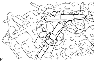
(a) Using a 45° cutter, resurface the valve seat so that the valve seat width is more than the specification. |
|
|
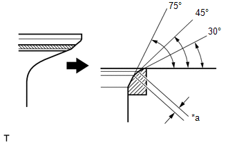
(b) Using 30° and 75° cutters, correct the exhaust valve seat so that the exhaust valve contacts the entire circumference of the seat. The contact should be in the center of the exhaust valve seat, and the exhaust valve seat width should be maintained within the specified range around the entire circumference of the exhaust valve seat. Text in Illustration
Standard width: 1.3 to 1.7 mm (0.0512 to 0.0669 in.) |
|
(c) Hand-lap the exhaust valve and exhaust valve seat with an abrasive compound.
(d) Check the exhaust valve seating position.
 Reassembly
REASSEMBLY
CAUTION / NOTICE / HINT
HINT:
Perform "Inspection After Repairs" after replacing the cylinder head sub-assembly
or cylinder head LH (See page ).
PROCEDURE
1. INSTALL SPARK ...

Other materials:
Disassembly
DISASSEMBLY
PROCEDURE
1. REMOVE OIL PUMP RELIEF VALVE
(a) Using a 27 mm socket wrench, remove the oil pump relief valve plug.
(b) Remove the oil pump relief valve spring and oil pump relief valve.
(c) Remove the spring and relief valve.
2. R ...
Terminals Of Ecm
TERMINALS OF ECM
1. ECM
HINT:
The standard voltage between each pair of ECM terminals is shown in the table
below. In the table, first follow the information under "Condition". Look under
"Terminal No. (Symbol)" for the terminals to be inspected. The standard voltage
b ...
Components
COMPONENTS
ILLUSTRATION
ILLUSTRATION
ILLUSTRATION
ILLUSTRATION
ILLUSTRATION
*A
w/ Seat Heater System
-
-
*1
FRONT SEAT CUSHION HEATER ASSEMBLY
*2
FRONT SEATBACK HEATER ASSEMBLY
...
