Toyota Tacoma (2015-2018) Service Manual: Repair
REPAIR
PROCEDURE
1. STEERING OFF CENTER REPAIR PROCEDURE
(a) Check if the steering wheel is off center.
|
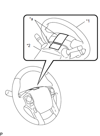
(1) Apply masking tape to the top center of the steering wheel and upper steering column cover. Text in Illustration
|
|
(2) Drive the vehicle in a straight line for 100 m (328 ft.) at a constant speed of 56 km/h (35 mph), and hold the steering wheel to maintain the course.
|
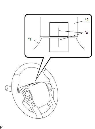
(3) Draw a line on the masking tape as shown in the illustration. Text in Illustration
|
|
(4) Turn the steering wheel to its straight position.
HINT:
Look at the upper surface of the steering wheel, steering spoke and SRS airbag line to find the center position.
|
(5) Draw a new line on the masking tape on the steering wheel as shown in the illustration. Text in Illustration
|
|
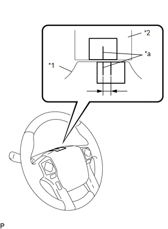
(6) Measure the distance between the 2 lines on the masking tape of the steering wheel.
(7) Convert the measured distance to the steering angle.
HINT:
- Measured distance 1 mm (0.0394 in.) = Steering angle of approximately 1°.
- Make a note of the steering angle.
(b) Adjust the steering angle.
|
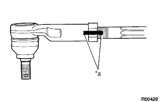
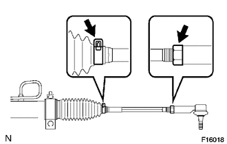
(1) Draw a line on the RH and LH tie rods and on the RH and LH rack ends which can easily be seen. Text in Illustration
|
|
(2) Using a paper gauge, measure the distance from a RH and LH tie rod ends to the rack end screws.
HINT:
- Measure both the RH and LH sides.
- Make a note of the measured values.
|
(3) Remove the RH and LH boot clips from the rack boots. |
|
(4) Loosen the RH and LH lock nuts.
(5) Turn the RH and LH rack ends by the same amount (but in different directions) according to the steering angle.
HINT:
One 360° turn of a rack end (1.5 mm (0.0591 in.) horizontal movement) is equal to a 12° change in steering angle.
(6) Tighten the RH and LH lock nuts.
Torque:
56 N·m {566 kgf·cm, 41 ft·lbf}
NOTICE:
Make sure that the difference in length between the RH and LH tie rod ends and rack end screws is less than 1.5 mm (0.059 in.).
(7) Install the RH and LH boot clips.
 Problem Symptoms Table
PROBLEM SYMPTOMS TABLE
HINT:
Use the table below to help determine the cause of problem symptoms. If multiple
suspected areas are listed, the potential causes of the symptoms are listed in order
...
 Air Conditioning
...
Other materials:
Pressure Control Solenoid "D" Electrical (Shift Solenoid Valve SLT) (P2716)
DESCRIPTION
Refer to the system description for DTC P2714 (See page
).
DTC No.
DTC Detection Condition
Trouble Area
P2716
Open or short is detected in shift solenoid valve SLT circuit for 1 second
or more while driving (1 trip dete ...
Precaution
PRECAUTION
1. CAUTION REGARDING INTERFERENCE WITH ELECTRONIC DEVICES
CAUTION:
People with implantable cardiac pacemakers, cardiac resynchronization
therapy-pacemakers or implantable cardioverter defibrillators should keep
away from the smart key system antennas. The radio waves ma ...
Vehicle Position Mark Deviates Greatly
CAUTION / NOTICE / HINT
NOTICE:
If standard size tires are not installed, the vehicle position mark
may deviate from the route even if the navigation system is operating normally.
Make sure that standard size tires are installed to the vehicle before
inspection.
PROCE ...
