Toyota Tacoma (2015-2018) Service Manual: Installation
INSTALLATION
PROCEDURE
1. INSTALL ENGINE WATER PUMP ASSEMBLY
|
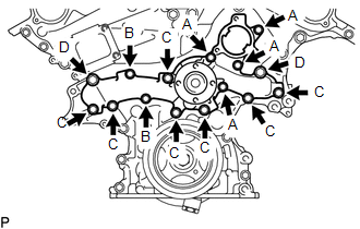
(a) Install the engine water pump assembly and a new gasket to the timing chain cover assembly with the 15 bolts. Torque: for Bolt A and B : 11 N·m {112 kgf·cm, 8 ft·lbf} for Bolt C : 21 N·m {214 kgf·cm, 15 ft·lbf} for Bolt D : 43 N·m {438 kgf·cm, 32 ft·lbf} NOTICE:
|
|
2. INSTALL NO. 2 IDLER PULLEY SUB-ASSEMBLY
(a) Install the 2 No. 2 idler pulley sub-assemblies to the timing chain cover assembly with the 2 bolts.
Torque:
43 N·m {438 kgf·cm, 32 ft·lbf}
3. INSTALL VANE PUMP ASSEMBLY
(a) Install the vane pump assembly to the timing chain cover assembly with the 2 bolts.
Torque:
21 N·m {214 kgf·cm, 15 ft·lbf}
4. INSTALL V-RIBBED BELT TENSIONER ASSEMBLY
.gif)
5. INSTALL COOLER COMPRESSOR ASSEMBLY
(See page )
6. INSTALL FAN SHROUD
7. INSTALL TRANSMISSION OIL COOLER HOSE (for Automatic Transmission)
|
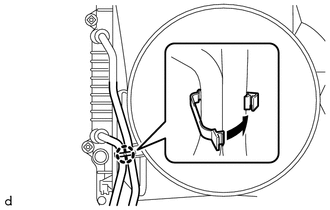
(a) Engage the clamp to install the 2 transmission oil cooler hoses to the fan shroud. |
|
8. CONNECT RADIATOR RESERVE TANK HOSE
9. INSTALL NO. 2 RADIATOR HOSE
10. INSTALL NO. 1 RADIATOR HOSE
11. INSTALL WATER INLET WITH THERMOSTAT SUB-ASSEMBLY
(See page )
 Removal
REMOVAL
PROCEDURE
1. REMOVE WATER INLET WITH THERMOSTAT SUB-ASSEMBLY
(See page )
2. REMOVE NO. 1 RADIATOR HOSE
3. REMOVE NO. 2 RADIATOR HOSE
4. DISCONNECT RADIATOR RESERVE TANK HOSE
5 ...

Other materials:
Terminals Of Ecu
TERMINALS OF ECU
Text in Illustration
*a
Component without harness connected
(Skid Control ECU [Brake Actuator Assembly])
-
-
Terminal No. (Symbol)
Terminal Description
1 (GND2)
Pump motor g ...
Screen Flicker or Color Distortion
PROCEDURE
1.
CHECK DISPLAY SETTING
(a) Reset display settings (contrast, brightness) and check that the screen appears
normal.
OK:
The display returns to normal.
OK
END
NG
PROCEED TO NEXT SUSPECTED AREA SHOWN IN ...
How To Proceed With Troubleshooting
CAUTION / NOTICE / HINT
HINT:
Use this procedure to troubleshoot the theft deterrent system.
*: Use the Techstream.
PROCEDURE
1.
VEHICLE BROUGHT TO WORKSHOP
NEXT
2.
...
