Toyota Tacoma (2015-2018) Service Manual: Removal
REMOVAL
CAUTION / NOTICE / HINT
NOTICE:
Replace the blind spot monitor sensor if it has been dropped or subjected to a severe impact.
PROCEDURE
1. REMOVE REAR BUMPER ASSEMBLY (w/ Towing Package)
(See page .gif) )
)
2. REMOVE REAR BUMPER ASSEMBLY (w/o Towing Package)
(See page )
3. REMOVE CONNECTOR COVER (w/ Towing Package)
(See page )
4. REMOVE REAR BUMPER HOLE COVER (w/o Towing Package)
(See page )
5. REMOVE REAR BUMPER PAD SUB-ASSEMBLY (w/ Towing Package)
(See page )
6. REMOVE REAR BUMPER PAD SUB-ASSEMBLY (w/o Towing Package)
(See page )
7. REMOVE REAR BUMPER EXTENSION LH (w/ Towing Package)
(See page )
8. REMOVE REAR BUMPER EXTENSION LH (w/o Towing Package)
(See page )
9. REMOVE REAR BUMPER EXTENSION RH (w/ Towing Package)
HINT:
Use the same procedure as for the LH side.
10. REMOVE REAR BUMPER EXTENSION RH (w/o Towing Package)
HINT:
Use the same procedure as for the LH side.
11. REMOVE BLIND SPOT MONITOR SENSOR LH
|
(a) Disconnect the connector. |
|
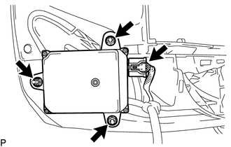
(b) Remove the 3 nuts and blind spot monitor sensor LH.
12. REMOVE BLIND SPOT MONITOR SENSOR RH
HINT:
Use the same procedure as for the LH side.
 Components
COMPONENTS
ILLUSTRATION
ILLUSTRATION
...
 Installation
INSTALLATION
CAUTION / NOTICE / HINT
NOTICE:
Replace the blind spot monitor sensor if it has been dropped or subjected to
a severe impact.
PROCEDURE
1. INSTALL BLIND SPOT MONITOR SENSOR LH
(a) ...
Other materials:
Inspection
INSPECTION
PROCEDURE
1. INSPECT RADIATOR CORE SUB-ASSEMBLY
Check the core plate for damage.
Text in Illustration
*1
Core Plate
*2
Radiator Core
If the sides of the core plate groove are deformed, it is impossible
to reassem ...
Check For Intermittent Problems
CHECK FOR INTERMITTENT PROBLEMS
1. CHECK FOR INTERMITTENT PROBLEMS
HINT:
A momentary interruption (open circuit) in the connectors and/or wire harnesses
between the sensors and ECUs can be detected using the ECU Data List function of
the Techstream.
(a) Turn the ignition switch off.
(b) Con ...
System Description
SYSTEM DESCRIPTION
1. POWER WINDOW CONTROL SYSTEM DESCRIPTION
(a) The power window control system controls the power window operation using
the power window regulator motors. The main controls of this system are the power
window regulator master switch assembly (mounted on the driver door), po ...
