Toyota Tacoma (2015-2018) Service Manual: Removal
REMOVAL
PROCEDURE
1. REMOVE LOWER INSTRUMENT PANEL FINISH PANEL SUB-ASSEMBLY RH
(See page .gif) )
)
2. REMOVE LOWER INSTRUMENT PANEL ASSEMBLY
(See page )
3. REMOVE AIR CONDITIONING CONTROL ASSEMBLY
(a) for Automatic Air Conditioning System (See page
)
(b) for Manual Air Conditioning System (See page
)
4. REMOVE FRONT CONSOLE BOX
(See page )
5. REMOVE NO. 2 INSTRUMENT PANEL GARNISH SUB-ASSEMBLY
(See page )
6. REMOVE INSTRUMENT PANEL LOWER CENTER FINISH PANEL
(See page )
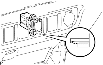
7. REMOVE NO. 1 STEREO JACK ADAPTER ASSEMBLY
|
(a) Disengage the 2 claws to remove the No. 1 stereo jack adapter assembly. |
|
 Components
COMPONENTS
ILLUSTRATION
...
 Installation
INSTALLATION
PROCEDURE
1. INSTALL NO. 1 STEREO JACK ADAPTER ASSEMBLY
(a) Engage the 2 claws to install the No. 1 stereo jack adapter assembly.
2. INSTALL INSTRUMENT PANEL LOWER CENTER FINISH PANEL ...
Other materials:
Torque Converter And Drive Plate
Inspection
INSPECTION
PROCEDURE
1. INSPECT TORQUE CONVERTER ASSEMBLY
(a) Inspect the one-way clutch.
(1) Press on the spline of the stator with a finger and rotate the spline. Check
that the spline rotates smoothly when turned clockwise and rotates with difficulty
when turned counterclock ...
Short in Driver Side Squib 2nd Step Circuit (B1810/53-B1813/53)
DESCRIPTION
The driver side squib 2nd step circuit consists of the airbag sensor assembly,
the spiral cable with sensor sub-assembly and the horn button assembly.
The circuit signals the SRS to deploy when airbag deployment conditions are met.
These DTCs are set when a malfunction is detected i ...
Driver Side Door Entry Unlock Function does not Operate
DESCRIPTION
If the entry unlock function does not operate for the driver door only, but the
entry lock function operates, the request code is being transmitted properly from
the driver door. In this case, there may be a problem related to the touch sensor
(connection between the certification ...
