Toyota Tacoma (2015-2018) Service Manual: Installation
INSTALLATION
PROCEDURE
1. INSTALL REAR SEAT 3 POINT TYPE OUTER BELT ASSEMBLY
|
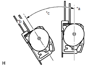
(a) Before installing the rear seat 3 point type outer belt assembly, check the ELR function. Text in Illustration
(1) When the inclination of the retractor is 15° or less, check that the belt can be pulled from the retractor. When the inclination of the retractor is over 45°, check that the belt locks. NOTICE: Do not disassemble the retractor. If operation is not as specified, replace the rear seat 3 point type outer belt assembly. |
|
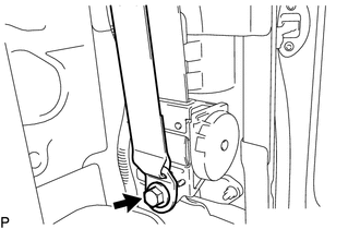
(b) Engage the 2 guides to install the rear seat 3 point type outer belt assembly with the bolt.
Torque:
12.5 N·m {127 kgf·cm, 9 ft·lbf}
(c) Tighten the bolt to connect the shoulder anchor.
Torque:
42 N·m {428 kgf·cm, 31 ft·lbf}
(d) Check that the shoulder anchor rotates smoothly.
|
(e) Connect the floor anchor with the bolt. Torque: 42 N·m {428 kgf·cm, 31 ft·lbf} |
|
(f) Check the ELR lock.
NOTICE:
The check should be performed with the rear seat 3 point type outer belt assembly installed.
(1) With the belt installed, check that the belt locks when it is pulled out quickly.
If the operation is not as specified, replace the rear seat 3 point type outer belt assembly.
(g) Remove the bolt to disconnect the floor anchor.
2. INSTALL QUARTER INSIDE TRIM BOARD
.gif)
3. CONNECT REAR SEAT 3 POINT TYPE OUTER BELT ASSEMBLY
4. INSTALL QUARTER TRIM LOWER PANEL
5. INSTALL ROOF SIDE INNER GARNISH
6. INSTALL ROOF SIDE INNER GARNISH CAP
7. CONNECT FRONT DOOR OPENING TRIM WEATHERSTRIP
8. INSTALL REAR DOOR SCUFF PLATE
9. INSTALL FRONT DOOR SCUFF PLATE
10. INSTALL BACK PANEL TRIM
11. INSTALL NO. 3 ROOM PARTITION COVER
12. INSTALL NO. 4 ROOM PARTITION COVER LH
13. INSTALL NO. 4 ROOM PARTITION COVER RH
14. INSTALL BACK PANEL GARNISH HOLE PLUG
15. INSTALL REAR SEAT CUSHION ASSEMBLY
 Components
COMPONENTS
ILLUSTRATION
ILLUSTRATION
...
 Removal
REMOVAL
PROCEDURE
1. REMOVE REAR SEAT CUSHION ASSEMBLY
2. REMOVE NO. 4 ROOM PARTITION COVER LH
3. REMOVE NO. 4 ROOM PARTITION COVER RH
4. REMOVE NO. 3 ROOM PARTITION COVER
5. REMO ...
Other materials:
Installation
INSTALLATION
PROCEDURE
1. INSTALL COOLER CONDENSER ASSEMBLY
(a) Engage the 2 claws to install the 2 condenser upper brackets.
(b) Engage the 2 claws to install the 2 condenser lower brackets.
(c) Lift the cooler condenser assembly up from the rear side of the vehicle,
and install ...
Sending Malfunction (Navigation to APGS) (U0073,U0100,U0129,U0140,U0155,U0164)
DESCRIPTION
These DTCs are stored when a malfunction occurs in the CAN communication circuit.
DTC Code
DTC Detection Condition
Trouble Area
U0073
CAN bus connection error
CAN communication system
U0100
...
Side Airbag Sensor LH Circuit Malfunction (B1625/22)
DESCRIPTION
The side airbag sensor assembly LH consists of parts such as the safing sensor,
the diagnostic circuit and the lateral deceleration sensor.
When the airbag sensor assembly receives signals from the lateral deceleration
sensor, it determines whether or not the SRS should be activate ...
