Toyota Tacoma (2015-2018) Service Manual: USB Audio System Recognition/Play Error
DESCRIPTION
When a USB device or "iPod" is connected to the USB jack of the No. 1 stereo jack adapter assembly, it must have playable files. The device must also communicate with and be recognized by the radio and display receiver assembly. This diagnosis procedure is for when a device is not recognized, or files from the device cannot be played normally.
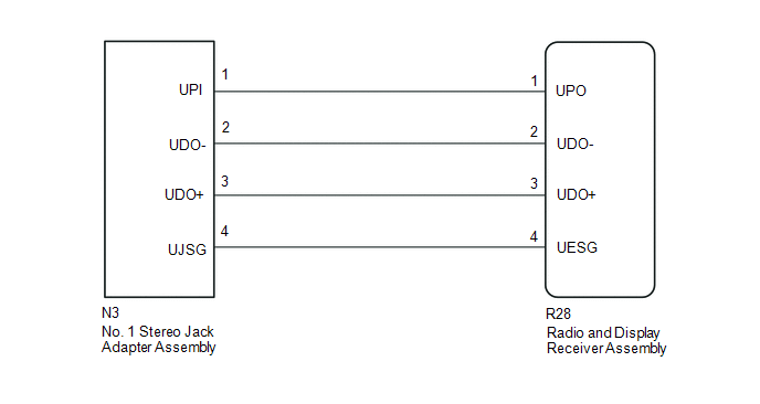
WIRING DIAGRAM
CAUTION / NOTICE / HINT
HINT:
- When a large amount of data is in a USB device, it may take a while to begin play.
- When using a USB device, files that are copy protected or encrypted due to copyright reasons cannot be played.
- When files are not played in the sorted order, perform the following
procedure before inspection.
- Add numbers in front of the file names.
- Put the files in a folder and copy the folder data to the USB device.
PROCEDURE
|
1. |
CHECK USB DEVICE OR "iPod" |
(a) Disconnect the USB device or "iPod" from the No. 1 stereo jack adapter assembly.
(b) Check if playable files are present on the USB device or "iPod".
HINT:
Refer to System Description for playable files (See page
.gif) ).
).
(c) Check if the USB device is a compatible format or "iPod" is a compatible version.
HINT:
Refer to System Description for compatible formats and versions (See page
).
|
Result |
Proceed to |
|---|---|
|
No playable files exist, or incompatible device format or version |
A |
|
No playable files exist, or incompatible device format or version |
B |
| A | .gif) |
USB DEVICE FORMAT WAS INCOMPATIBLE, "iPod" VERSION WAS INCOMPATIBLE, OR NO PLAYABLE FILES PRESENT |
|
.gif)
|
2. |
CHECK HARNESS AND CONNECTOR (RADIO AND DISPLAY RECEIVER ASSEMBLY - NO. 1 STEREO JACK ADAPTER ASSEMBLY) |
(a) Disconnect the R28 radio and display receiver assembly connector.
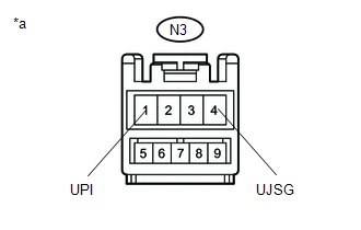
(b) Disconnect the N3 No. 1 stereo jack adapter assembly connector.
(c) Measure the resistance according to the value(s) in the table below.
Standard Resistance:
|
Tester Connection |
Condition |
Specified Condition |
|---|---|---|
|
N3-1 (UPI) - R28-1 (UPO) |
Always |
Below 1 Ω |
|
N3-2 (UDO-) - R28-2 (UDO-) |
Always |
Below 1 Ω |
|
N3-3 (UDO+) - R28-3 (UDO+) |
Always |
Below 1 Ω |
|
N3-4 (UJSG) - R28-4 (UESG) |
Always |
Below 1 Ω |
|
N3-1 (UPI) - Body ground |
Always |
10 kΩ or higher |
|
N3-2 (UDO-) - Body ground |
Always |
10 kΩ or higher |
|
N3-3 (UDO+) - Body ground |
Always |
10 kΩ or higher |
|
N3-4 (UJSG) - Body ground |
Always |
10 kΩ or higher |
| NG | |
REPAIR OR REPLACE HARNESS OR CONNECTOR |
|
|
3. |
INSPECT RADIO AND DISPLAY RECEIVER ASSEMBLY (NO. 1 STEREO JACK ADAPTER ASSEMBLY POWER SOURCE) |
(a) Reconnect the radio and display receiver assembly connector.
|
(b) Measure the voltage according to the value(s) in the table below. Standard Voltage:
|
|
| NG | |
REPLACE RADIO AND DISPLAY RECEIVER ASSEMBLY |
|
|
4. |
FORMAT USB DEVICE OR RESTORE "iPod" AND RECHECK |
(a) Delete all files in the USB device or "iPod" and format/restore it.
(b) Save the data again and check if it can be played on the in-vehicle device.
NOTICE:
Formatting a USB device or restoring an "iPod" erases all music on the device. Ensure that backup music data is available before performing this operation.
OK:
Malfunction disappears.
| OK | |
END |
|
|
5. |
REPLACE USB DEVICE OR "iPod" |
(a) Turn the ignition switch off.
HINT:
When this malfunction occurs, it is necessary to turn off the ignition switch to make it possible for the vehicle to recognize a new device when it is connected.
(b) Turn the ignition switch ACC.
(c) Connect a known good USB device or "iPod" to the No. 1 stereo jack adapter assembly.
HINT:
- If the malfunction occurred when a USB device was in use, use another USB device for the inspection. If the malfunction occurred when an "iPod" was in use, use another "iPod" for the inspection.
- Refer to System Description for compatible formats and versions (See
page ).
|
|
6. |
CHECK USB DEVICE OR "iPod" |
(a) Check if a USB device or "iPod" is recognized by the radio and display receiver assembly, and if information such as track, artist and album names are displayed on the screen.
OK:
Malfunction disappears.
| OK | |
USB DEVICE OR "iPod" WAS INCOMPATIBLE OR DEFECTIVE |
| NG | |
PROCEED TO NEXT SUSPECTED AREA SHOWN IN PROBLEM SYMPTOMS TABLE |
 Portable Player cannot be Registered
CAUTION / NOTICE / HINT
HINT:
Some versions of "Bluetooth" compatible audio players may not function, or the
function may be limited using the radio and display receiver assembly, even i ...
 Black Screen
PROCEDURE
1.
CHECK DISPLAY SETTING
(a) Check that the display is not in "Screen Off" mode.
OK:
The display setting is not in "Screen Off" mode. ...
Other materials:
Installation
INSTALLATION
PROCEDURE
1. INSTALL FUEL SUCTION TUBE SET GASKET
(a) Ensure gasket groove is clean and free of foreign particles.
(b) Install a new gasket onto the fuel tank.
(c) Make sure that the gasket sits in the groove.
2. INSTALL FUEL SU ...
Transmission Fluid Temperature Sensor "A" Circuit Low Input (P0712,P0713)
DESCRIPTION
The No. 1 ATF temperature sensor converts the fluid temperature into a resistance
value for use by the ECM.
The ECM applies a voltage to the temperature sensor through terminal THO1 of
the ECM.
The sensor resistance changes with the ATF temperature. As the temperature becomes
hi ...
Steering Pad Switch Circuit
DESCRIPTION
This circuit sends an operation signal from the steering pad switch assembly
to the navigation receiver assembly.
If there is an open in the circuit, the audio system cannot be operated using
the steering pad switch assembly.
If there is a short in the circuit, the same condition ...
