Toyota Tacoma (2015-2018) Service Manual: Removal
REMOVAL
CAUTION / NOTICE / HINT
HINT:
- Use the same procedure for the RH side and LH side.
- The following procedure is for the LH side.
- When removing the front fender wheel opening moulding or quarter panel wheel opening moulding, heat the vehicle body and front fender wheel opening moulding or quarter panel wheel opening moulding using a heat light.
|
Item |
Temperature |
|---|---|
|
Vehicle Body |
40 to 60°C (104 to 140°F) |
|
Front Fender Wheel Opening Moulding or Quarter Panel Wheel Opening Moulding |
20 to 30°C (68 to 86°F) |
NOTICE:
Do not heat the vehicle body or front fender wheel opening moulding or quarter panel wheel opening moulding excessively.
PROCEDURE
1. REMOVE FRONT FENDER MUDGUARD (w/ Mudguard)
(See page .gif) )
)
2. REMOVE FRONT FENDER WHEEL OPENING MOULDING (w/ Mudguard)
|
(a) Using a heat light, heat the front fender wheel opening moulding. |
|
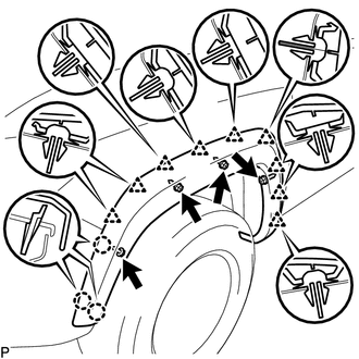
(b) Remove the 4 screws.
(c) Disengage the 3 claws and 9 clips, and peel off the double-sided tape to remove the front fender wheel opening moulding.
3. REMOVE FRONT FENDER WHEEL OPENING MOULDING (w/o Mudguard)
|
(a) Using a heat light, heat the front fender wheel opening moulding. |
|
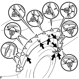
(b) Remove the 7 screws.
(c) Disengage the 3 claws and 9 clips, and peel off the double-sided tape to remove the front fender wheel opening moulding.
4. REMOVE REAR QUARTER PANEL MUDGUARD (w/ Mudguard)
(See page )
5. REMOVE QUARTER PANEL WHEEL OPENING MOULDING (w/ Mudguard)
|
(a) Using a heat light, heat the quarter panel wheel opening moulding. |
|
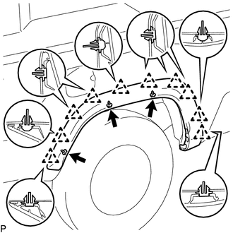
(b) Remove the 3 screws.
(c) Disengage the 10 clips, and peel off the double-sided tape to remove the quarter panel wheel opening moulding.
6. REMOVE QUARTER PANEL WHEEL OPENING MOULDING (w/o Mudguard)
|
(a) Using a heat light, heat the quarter panel wheel opening moulding. |
|
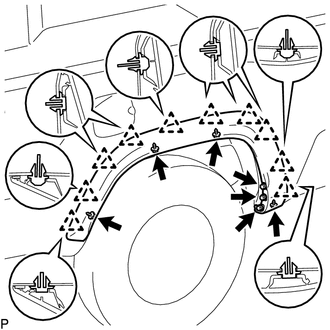
(b) Remove the 7 screws.
(c) Disengage the 10 clips, and peel off the double-sided tape to remove the quarter panel wheel opening moulding.
 Reassembly
REASSEMBLY
CAUTION / NOTICE / HINT
HINT:
Use the same procedure for the RH side and LH side.
The following procedure is for the LH side.
When installing a new front wheel opening ex ...
 Installation
INSTALLATION
CAUTION / NOTICE / HINT
HINT:
Use the same procedure for the RH side and LH side.
The following procedure is for the LH side.
When installing a new front fender wheel o ...
Other materials:
Diagnosis System
DIAGNOSIS SYSTEM
1. DESCRIPTION
The ECM stores DTCs (Diagnostic Trouble Codes) when trouble occurs on the vehicle.
The diagnosis system allows reading of DTCs stored in the ECM when a the Techstream
is connected to the DLC3 (Data Link Connector 3). If the CRUISE MAIN indicator light
does not ...
Open in Occupant Classification ECU Battery Positive Line (B1794)
DESCRIPTION
DTC B1794 is set when a malfunction is detected in the occupant detection ECU.
DTC No.
DTC Detections Conditions
Trouble Areas
B1794
Occupant detection ECU circuit malfunction
Occupant detection ECU malfuncti ...
System Diagram
SYSTEM DIAGRAM
Communication Table
Sender
Receiver
Signal
Line
ECM
Millimeter Wave Radar Sensor Assembly
Cruise control operation signal
Accelerator pedal idle position signal
Accel overr ...
