Toyota Tacoma (2015-2018) Service Manual: Initialization Switch (for Test Mode DTC) (C2198/98)
DESCRIPTION
During test mode, when the tire pressure warning reset switch is on, the tire pressure warning light comes on and when the tire pressure warning reset switch is off, the tire pressure warning light blinks at 0.125 second intervals.
|
DTC No. |
DTC Detection Condition |
Trouble Area |
|---|---|---|
|
C2198/98 |
Test mode procedure is performed. |
|
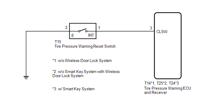
WIRING DIAGRAM
CAUTION / NOTICE / HINT
NOTICE:
- When replacing the tire pressure warning ECU and receiver, read the transmitter IDs stored in the old ECU using the Techstream and write them down before removal.
- It is necessary to perform initialization (See page
.gif) ) after registration (See page
) of the transmitter IDs into the tire
pressure warning ECU and receiver if the ECU has been replaced.
) after registration (See page
) of the transmitter IDs into the tire
pressure warning ECU and receiver if the ECU has been replaced.
PROCEDURE
|
1. |
INSPECT TIRE PRESSURE WARNING RESET SWITCH |
|
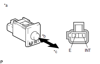
(a) Disconnect the T15 tire pressure warning reset switch connector. |
|
(b) Measure the resistance according to the value(s) in the table below.
Standard Resistance:
|
Tester Connection |
Switch Condition |
Specified Condition |
|---|---|---|
|
1 (INT) - 2 (E) |
On |
Below 1 Ω |
|
Off |
10 kΩ or higher |
|
*a |
Component without harness connected (Tire Pressure Warning Reset Switch) |
|
*b |
On |
|
*c |
Off |
| NG | .gif) |
REPLACE TIRE PRESSURE WARNING RESET SWITCH |
|
.gif)
|
2. |
CHECK HARNESS AND CONNECTOR (TIRE PRESSURE WARNING RESET SWITCH - TIRE PRESSURE WARNING ECU AND RECEIVER) |
(a) Disconnect the T15 tire pressure warning reset switch connector and T14 tire pressure warning ECU and receiver connector.
(b) Measure the resistance according to the value(s) in the table below.
Standard Resistance:
|
Tester Connection |
Condition |
Specified Condition |
|---|---|---|
|
T14-3 (CLSW) - T15-1 (INT) |
Always |
Below 1 Ω |
|
T14-3 (CLSW) - Body ground |
Always |
10 kΩ or higher |
|
T15-2 (E) - Body ground |
Always |
Below 1 Ω |
| OK | |
REPLACE TIRE PRESSURE WARNING ECU AND RECEIVER |
| NG | |
REPAIR OR REPLACE HARNESS OR CONNECTOR |
 Tire Pressure Monitor ECU Communication Stop (C2179/79)
DESCRIPTION
The main body ECU (multiplex network body ECU) sends signals to the tire pressure
warning ECU and receiver via a direct line.
DTC No.
Detection Item
DT ...
 Tire Pressure Monitor Receiver Communication Stop (B1247)
DESCRIPTION
The main body ECU (multiplex network body ECU) and tire pressure warning ECU
and receiver are connected using 2 direct lines that they use to communicate with
each other.
...
Other materials:
Diagnosis System
DIAGNOSIS SYSTEM
1. DESCRIPTION
(a) Air conditioning system data and the Diagnostic Trouble Codes (DTCs) can
be read through the Data Link Connector 3 (DLC3) of the vehicle. When the system
seems to be malfunctioning, use the Techstream to check for malfunctions and perform
troubleshooting.
...
Front Camera Module Incorrect Axial Gap (C1AA8,C1AA9)
DESCRIPTION
If the forward recognition camera detects that the forward recognition camera
axis has deviated, DTC C1AA8 is stored. Also, if Forward Recognition Camera Axis
Adjustment is not performed after installing the forward recognition camera, DTC
C1AA9 is stored.
DTC No.
...
Stop Light Switch OFF Stuck Malfunction (C1426)
DESCRIPTION
The skid control ECU (brake actuator assembly) inputs the stop light signal and
brake operation condition. When the brake pedal is depressed and the stop light
switch signal is not input, C1426 is output.
DTC No.
Detection Item
DTC Detection Conditi ...
